NDS03ZE-M6 POWER ONE, NDS03ZE-M6 Datasheet - Page 9
NDS03ZE-M6
Manufacturer Part Number
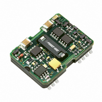
NDS03ZE-M6
Description
CONV DC-DC 48V IN 3.3V OUT 10W
Manufacturer
POWER ONE
Series
NDSr
Type
Isolatedr
Datasheet
1.NDS03ZE-M6.pdf
(14 pages)
Specifications of NDS03ZE-M6
Output
3.3V
Number Of Outputs
1
Power (watts)
10W
Mounting Type
Surface Mount
Voltage - Input
36 ~ 75V
Package / Case
24-DIP SMD Module (14 Leads)
1st Output
3.3 VDC @ 3A
Size / Dimension
1.30" L x 0.91" W x 0.33" H (33mm x 23.1mm x 8.4mm)
Power (watts) - Rated
10W
Operating Temperature
-40°C ~ 100°C
Efficiency
85%
Approvals
CSA, EN, UL
Product
Isolated
Output Power
10 W
Input Voltage Range
36 V to 75 V
Output Voltage (channel 1)
3.3 V
Output Current (channel 1)
3 A
Isolation Voltage
1500 V
Package / Case Size
SOIC-24
Output Type
Isolated
Output Current
3A
Input Voltage
36 to 75V
Output Voltage
3.3V
Screening Level
Industrial
Product Length (mm)
33mm
Product Height (mm)
8.5mm
Mounting Style
Surface Mount
Pin Count
14
Lead Free Status / RoHS Status
Contains lead / RoHS non-compliant
3rd Output
-
2nd Output
-
4th Output
-
Lead Free Status / Rohs Status
Lead free / RoHS Compliant
Other names
179-2191


Application and Auxiliary Functions
This series of converters does not require any external
components for proper operation. However, if the
distribution of the input voltage to the converter
contains significant inductance, a capacitor across the
input terminals may be required to stabilize the input
voltage. A minimum of 1 μF, quality electrolytic /
ceramic capacitor is recommended for this purpose.
For output decoupling it is recommend connecting a
1 μF ceramic capacitor directly across the output pins
of the converter.
Shutdown Feature
The remote control pin functions as a normal soft
shutdown. It is referenced to the –Vi pin. With positive
logic, when the remote control pin is pulled low, the
output is turned off and the unit goes into a very low
input power mode.
An open collector switch is recommended to control
the voltage between the remote control pin and the
–Vi pin of the converter. The remote control pin is
pulled up internally, so no external voltage source is
required. The user should avoid connecting a resistor
between the remote control pin and the +Vi pin.
The user must take care to ensure that the pin
reference for the control is connected close to the –Vi
pin. The control signal must not be referenced ahead
of EMI filtering, or remotely from the unit. If the remote
control pin is not used, it can be left floating.
Thermal Considerations
The converter is designed for natural or forced
convection cooling. The output power of the converter
is limited by the maximum case temperature (T
ensure reliable long term operation of the converters,
and to comply with safety agency requirements,
Power-One
temperature (T
Parallel Operation
Paralleling of two converters is not possible.
BCD.00013 Rev. AB, 26-Aug-2010
limits
c
) to 100 °C; see Mechanical Drawings.
maximum
allowable
c
). To
case
10 W SMT DC-DC Converters, 1.5 – 5 V Output
Page 9 of 14
Output Current Limitation
When the output is overloaded above the maximum
output current rating, the voltage will start to reduce to
maintain the output power to a safe level. In a
condition of high overload or short-circuit, where the
output voltage is pulled below approximately 30% of
Vo.Nom, the unit will enter a ‘Hiccup’ mode of
operation. Under this condition the unit will attempt to
restart, approximately every 25 ms, until the overload
has cleared.
Output Voltage Adjustment
The trim feature allows the user for adjusting the
output voltage by means of an external resistor. To
increase V
pins 12 and 14. To decrease V
connected between pins 12 and 13.
To increase V
To reduce V
Where V
NDS03ZA
NDS03ZB
NDS03ZD
NDS02ZG
Model
NDS03ZE
Note: When the output voltage is trimmed up, the
output power from the converter must not exceed its
maximum rating. This is determined by measuring the
voltage on the output pins, and multiplying it by the
output current.
Rext = (A – (D x V
Rext = ((B x V
o
is the desired output voltage
o
a resistor should be connected between
o
:
o
11260
:
1945
2590
5010
7010
A
o
) – C) / (V
o
NDS Series Data Sheet
)) / ( V
1470
1730
2516
3161
4532
B
o nom
o
– V
o
– V
o nom
a resistor should be
11240
www.power-one.com
1944
2560
5010
7010
o
C
), [Ω]
) [Ω]
1500
1500
1500
470
750
D
Related parts for NDS03ZE-M6
Image
Part Number
Description
Manufacturer
Datasheet
Request
R

Part Number:
Description:
SWITCHING POWER SUPPLIES, SINGLE OUTPUT, 80 WATTS
Manufacturer:
POWER ONE
Datasheet:
Part Number:
Description:
HAS SERIES - 30 WATT
Manufacturer:
POWER ONE
Datasheet:
Part Number:
Description:
SINGLE OUTPUT
Manufacturer:
POWER ONE
Datasheet:

Part Number:
Description:
BRS DC/DC converters(1.5 WATT)
Manufacturer:
Power-One
Datasheet:
Part Number:
Description:
3...15 Watt DC-DC Converter
Manufacturer:
Power-One
Datasheet:
Part Number:
Description:
HBS SERIES - 100 WATT
Manufacturer:
Power-One
Datasheet:
Part Number:
Description:
3...15 Watt DC-DC Converter
Manufacturer:
Power-One
Datasheet:
Part Number:
Description:
BUS DC/DC converters(3 WATT)
Manufacturer:
Power-One
Datasheet:
Part Number:
Description:
HES SERIES 150 WATT
Manufacturer:
Power-One
Datasheet:
Part Number:
Description:
1.25 WATT
Manufacturer:
Power-One
Datasheet: