UCH-3.3/30-D48NB-C Murata Power Solutions Inc, UCH-3.3/30-D48NB-C Datasheet - Page 11
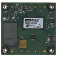
UCH-3.3/30-D48NB-C
Manufacturer Part Number
UCH-3.3/30-D48NB-C
Description
CONV DC/DC 99W 3.3V 30A
Manufacturer
Murata Power Solutions Inc
Series
UCHr
Type
Isolatedr
Datasheet
1.UCH-3.310-D48NB-C.pdf
(18 pages)
Specifications of UCH-3.3/30-D48NB-C
Output
3.3V
Number Of Outputs
1
Power (watts)
99W
Mounting Type
Through Hole
Voltage - Input
36 ~ 75V
Package / Case
9-DIP Module, 1/2 Brick
1st Output
3.3 VDC @ 30A
Size / Dimension
2.40" L x 2.30" W x 0.40" H (61mm x 58.4mm x 10.2mm)
Power (watts) - Rated
99W
Operating Temperature
-40°C ~ 85°C
Efficiency
90%
Approvals
CSA, EN, UL
Output Power
99 W
Input Voltage Range
36 V to 75 V
Output Voltage (channel 1)
3.3 V
Output Current (channel 1)
30 A
Isolation Voltage
2.25 KV
Product
Isolated
Input Voltage (nominal)
48 V
Package / Case Size
C61
Output Type
Isolated Single
Output Voltage
3.3 V
Lead Free Status / RoHS Status
Lead free / RoHS Compliant
3rd Output
-
2nd Output
-
4th Output
-
Lead Free Status / Rohs Status
Lead free / RoHS Compliant
Other names
811-1847-5


Since these are isolated DC/DC converters, their outputs are “fl oating” with
respect to their input. The essential feature of such isolation is ideal ZERO
CURRENT FLOW between input and output. Real-world converters however do
exhibit tiny leakage currents between input and output (see Specifi cations).
These leakages consist of both an AC stray capacitance coupling component
and a DC leakage resistance. When using the isolation feature, do not allow
the isolation voltage to exceed specifi cations. Otherwise the converter may
be damaged. Designers will normally use the negative output (-Output) as
the ground return of the load circuit. You can however use the positive output
(+Output) as the ground return to effectively reverse the output polarity.
All models regulate within specifi cation and are stable under no load to full
load conditions. Operation under no load might however slightly increase
output ripple and noise.
To prevent many over temperature problems and damage, these converters
include thermal shutdown circuitry. If environmental conditions cause the
temperature of the DC/DC’s to rise above the Operating Temperature Range
up to the shutdown temperature, an on-board electronic temperature sensor
will power down the unit. When the temperature decreases below the turn-on
threshold, the converter will automatically restart. There is a small amount of
hysteresis to prevent rapid on/off cycling. The temperature sensor is typically
located adjacent to the switching controller, approximately in the center of the
unit. See the Performance and Functional Specifi cations.
shut down suddenly without warning. Be sure to thoroughly test your applica-
tion to avoid unplanned thermal shutdown.
The graphs in the next section illustrate typical operation under a variety of
conditions. The Derating curves show the maximum continuous ambient air
temperature and decreasing maximum output current which is acceptable
under increasing forced airfl ow measured in Linear Feet per Minute (“LFM”).
Note that these are AVERAGE measurements. The converter will accept brief
increases in current or reduced airfl ow as long as the average is not exceeded.
+OUTPUT
−OUTPUT
If you operate too close to the thermal limits, the converter may
+SENSE
−SENSE
C1 = 0.1μF CERAMIC
C2 = 10μF TANTALUM
LOAD 2-3 INCHES (51-76mm) FROM MODULE
6
5
9
8
C1
COPPER STRIP
COPPER STRIP
C2
SCOPE
www.murata-ps.com
R
LOAD
itself which is obviously running at higher temperature than the outside air.
Also note that very low fl ow rates (below about 25 LFM) are similar to “natural
convection,” that is, not using fan-forced airfl ow.
cycle wind tunnel with calibrated airfl ow. We use both thermocouples and an
infrared camera system to observe thermal performance. As a practical matter,
it is quite diffi cult to insert an anemometer to precisely measure airfl ow in
most applications. Sometimes it is possible to estimate the effective airfl ow if
you thoroughly understand the enclosure geometry, entry/exit orifi ce areas and
the fan fl owrate specifi cations.
the converter may have an unplanned Over Temperature shut down. Also, these
graphs are all collected at slightly above Sea Level altitude. Be sure to reduce
the derating for higher density altitude.
This converter monitors its output voltage for an over-voltage condition. If
the output exceeds OVP limits, the sensing circuit will power down the unit,
and the output voltage will decrease. After a time-out period, the PWM will
automatically attempt to restart, causing the output voltage to ramp up to its
rated value. It is not necessary to power down and reset the converter for the
automatic OVP-recovery restart.
levels, the OVP circuitry will initiate another shutdown cycle. This on/off cycling
is referred to as “hiccup” mode. It safely tests full current rated output voltage
without damaging the converter.
The converter is extensively protected against current, voltage and temperature
extremes. However your output application circuit may need additional protec-
tion. In the extremely unlikely event of output circuit failure, excessive voltage
could be applied to your circuit. Consider using an appropriate fuse in series
with the output.
As soon as the output current increases to approximately 125% to 150% of
its maximum rated value, the DC/DC converter will enter a current-limiting
mode. The output voltage will decrease proportionally with increases in output
current, thereby maintaining a somewhat constant power output. This is also
commonly referred to as power limiting.
below the rated tolerance. See the Performance/Functional Specifi cations.
Note particularly that the output current may briefl y rise above its rated value
in normal operation as long as the average output power is not exceeded. This
enhances reliability and continued operation of your application. If the output
current is too high, the converter will enter the short circuit condition.
When a converter is in current-limit mode, the output voltage will drop as the
output current demand increases. If the output voltage drops too low (ap-
proximately 98% of nominal output voltage for most models), the magnetically
Note that the temperatures are of the ambient airfl ow, not the converter
Murata Power Solutions makes Characterization measurements in a closed
If the fault condition persists and the output voltage climbs to excessive
Current limiting inception is defi ned as the point at which full power falls
If you routinely or accidentally exceed these Derating guidelines,
1.8−15V Output DC/DC Converters
Isolated, “Half-Brick”
Page 11 of 18
Related parts for UCH-3.3/30-D48NB-C
Image
Part Number
Description
Manufacturer
Datasheet
Request
R

Part Number:
Description:
DC/DC Converters & Regulators 3.3Vout 30A 99W 48Vin Neg Polarity
Manufacturer:
Murata Power Solutions Inc
Datasheet:

Part Number:
Description:
CONV DC/DC 33W 3.3V 10A
Manufacturer:
Murata Power Solutions Inc
Datasheet:

Part Number:
Description:
CONV DC/DC 33W 3.3V 10A
Manufacturer:
Murata Power Solutions Inc
Datasheet:

Part Number:
Description:
CONV DC/DC 49.5W 3.3V 15A
Manufacturer:
Murata Power Solutions Inc
Datasheet:

Part Number:
Description:
CONV DC/DC 115.5W 3.3V 35A
Manufacturer:
Murata Power Solutions Inc
Datasheet:
Part Number:
Description:
DC/DC Converters & Regulators 3.3Vout 10A 33W 24Vin Pos Polarity
Manufacturer:
Murata Power Solutions Inc
Datasheet:
Part Number:
Description:
DC/DC Converters & Regulators 3.3Vout 15A 49.5W 48Vin Neg Polarity
Manufacturer:
Murata Power Solutions Inc
Datasheet:
Part Number:
Description:
DC/DC Converters & Regulators 3.3Vout 10A 33W 48Vin Neg Polarity
Manufacturer:
Murata Power Solutions Inc
Datasheet:

Part Number:
Description:
CONV DC/DC 150W 12V 12.5A
Manufacturer:
Murata Power Solutions Inc
Datasheet:

Part Number:
Description:
Transformers 5Vin 5Vout 200mA 4000Vdc 1:1.33 turn
Manufacturer:
Murata Power Solutions Inc
Datasheet:

Part Number:
Description:
POWER SUPPLY
Manufacturer:
Murata Power Solutions Inc
Datasheet:

Part Number:
Description:
DPM LED MINI 2VDC 3.5DIG LP RED
Manufacturer:
Murata Power Solutions Inc
Datasheet:

Part Number:
Description:
CONV DC/DC 1W 5VIN 5VOUT SIP SGL
Manufacturer:
Murata Power Solutions Inc
Datasheet: