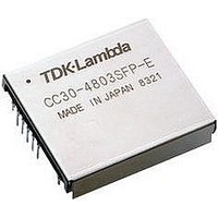
CC30-2405SRP-E TDK Corporation, CC30-2405SRP-E Datasheet

CC30-2405SRP-E
Specifications of CC30-2405SRP-E
Related parts for CC30-2405SRP-E
CC30-2405SRP-E Summary of contents
Page 1
... CC15 CC15 xxxxSxx CC15 CC15 xxxxSxx xxxxSxx CC30 xxxxSxx E , CC30 xxxxSxxx E , CC30 E , CC30 1. Standard Connection Method 1. Standard Connection Method 1. Standard Connection Method 1. Standard Connection Method The connection method shown in Figure 1. DC Input Fuse When not using the Remote Control function, use it with either the RC terminal open or connected to the –Vin terminal. ...
Page 2
... Table 3-1 Recommended Fuse Capacity CC15-24xxSxx-E 2A CC15-48xxSxx-E 1A Lin Cin Fuse Cin Fuse Fig. 3-2-2 Cin is necessary when the input line is long. Table 3-2 Recommended External Capacitor Cin Values CC15-24xxSxx-E 33μF CC15-48xxSxx-E 10μF CC30-24xxSxx-E 4A CC30-48xxSxx-E 2A +Vin -Vin +Vin -Vin CC30-24xxSxx-E 68μF CC30-48xxSxx-E 22μF ...
Page 3
Input Ripple Noise Voltage Reduction (Noise Terminal Voltage Reduction) This converter has a built-in input filter circuit, in addition, by connecting an input filter as shown in Figure 3-3, input ripple noise voltage (noise terminal voltage) can be decreased. ...
Page 4
Output Ripple Noise Voltage Measurement Method When measuring the output ripple noise voltage of this converter, the value differs greatly, depending on the measurement method. Measurement made close to the output terminal, do not make a ...
Page 5
Terminal Function / Protection Function / Series Connection 4. Terminal Function / Protection Function / Series 4. Terminal Function / Protection Function / Series 4. Terminal Function / Protection Function / Series 4-1 Remote Control (RC Terminal) When the ...
Page 6
Alarm (ALM Terminal) By means of the ALM terminal the presence / absence of an abnormal state can be monitored. When not using the alarm output function, set the ALM terminal in the open condition. When the output turns ...
Page 7
Over-Current Protection (OCP) & Low-Voltage Protection (LVP) These converters are equipped with built-in over-current protection and low-voltage protection circuits. When the output current exceeds the over-current setting point the over-current protection circuit operates and the output voltage begins to ...
Page 8
Series Operation For this converter series possible to operate models of the same type in series. The maximum number of converters which can be operated in series is 2. When using series operation, connect the +Vin terminal ...
Page 9
Parallel Operation For this converter series possible to operate models of the same type in parallel. The maximum number of converters which can be operated in parallel is 10. When using parallel operation, connect the PO terminal ...
Page 10
Soldering Conditions / Cleaning Conditions / Installation Method 5. Soldering Conditions / Cleaning Condi 5. Soldering Conditions / Cleaning Condi 5. Soldering Conditions / Cleaning Condi 5-1 Soldering Conditions 【DIP Model】 Perform soldering of the converter to the board ...
Page 11
... When installing the converter on the board, avoid having trace pattern, etc. in the slanted line area shown in Figure 5-3 because there is the possibility of an insulation defect occurring. 1.75 34.7 38.2 CC15-xxxxxSx-E ※Contact TDK-Lambda concerning items not mentioned or items which are not clear. 1.75 (1.75) Out line CC30-xxxxxSx-E Fig. 5-2 Trace Pattern Prohibited Area 34.7 (1.75) Out line 38.2 ...


