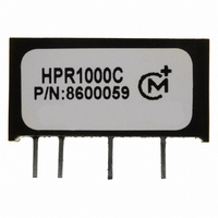
HPR1000C Murata Power Solutions Inc, HPR1000C Datasheet - Page 2

HPR1000C
Manufacturer Part Number
HPR1000C
Description
CONV DC/DC 5V 200MA SIP
Manufacturer
Murata Power Solutions Inc
Series
HPR10xxCr
Type
Isolatedr
Datasheet
1.HPR1023C.pdf
(4 pages)
Specifications of HPR1000C
Output
5V
Number Of Outputs
1
Power (watts)
1W
Mounting Type
Through Hole
Voltage - Input
4.5 ~ 5.5V
Package / Case
7-SIP Module (5 Leads)
1st Output
5 VDC @ 200mA
Size / Dimension
0.77" L x 0.24" W x 0.40" H (19.6mm x 6.1mm x 10.2mm)
Power (watts) - Rated
1W
Operating Temperature
-25°C ~ 65°C
Efficiency
68%
Dc / Dc Converter O/p Type
Fixed
No. Of Outputs
1
Input Voltage
4.5V To 5.5V
Power Rating
1W
Output Voltage
5V
Output Current
200mA
Supply Voltage
5V
Dc / Dc Converter Case Style
SIP
Product
Isolated
Output Power
1 W
Input Voltage Range
4.5 V to 5.5 V
Input Voltage (nominal)
5 V
Output Voltage (channel 1)
5 V
Output Current (channel 1)
200 mA
Isolation Voltage
1 KV
Package / Case Size
SIP
Lead Free Status / RoHS Status
Lead free / RoHS Compliant
3rd Output
-
2nd Output
-
4th Output
-
Lead Free Status / Rohs Status
Details
Other names
811-1757-5
www.murata-ps.com
MECHANICAL
BOTTOM
FRONT
VIEW
VIEW
Specifi cations typical at T
* For demonstrated MTTF results reference Reliability Report HPR105
COMMON SPECIFICATIONS
TEMPERATURE
INPUT
Voltage Range
Voltage Rise Time
ISOLATION
Rated Voltage
Test Voltage
Resistance
Capacitance
Leakage Current
OUTPUT
Rated Power
Voltage Setpoint Accuracy
Ripple & Noise
Voltage
Temperature Coeffi cent
REGULATION
Line Regulation
Load Regulation (5V out only)
Load Regulation (All other Models)
GENERAL
Switching Frequency
Frequency Change
Package Weight
MTTF per MIL-HDBK-217, Rev. E
Ground Benign
Fixed Ground
Naval Sheltered
Airborne Uninhabited Fighter
Specifi cation
Storage
PARAMETER
HPR10XXC
A
= +25°C, nominal input voltage, rated output current unless otherwise specifi ed.
Rated Load to 1mA Load
Rated Load to 1mA Load
Rated Load, Nominal V
PIN CONNECTIONS
1. +VIN
4. -VOUT 5. COM*
1mA Load, V
1mA Load, V
High Line to Low Line
1mA Load, V
Circuit Stress Method
V
BW = DC to 10MHz
BW =10Hz to 2MHz
Over Line and Load
See Typical Performance Curves & Application Notes: "Capacitive Loading Effects on Start-Up of DC/DC Converters"
60 Hz, 10 Seconds
ISO
CONDITIONS
6. +VOUT
= 240VAC, 60Hz
T
T
T
T
A
A
A
A
= +25°C
= +35°C
= +35°C
= +35°C
2. -VIN
OUT
OUT
OUT
= 12V
= 15V
= 5V
*
IN
Common pin not present on single output models.
MIN
1000
1000
10.8
13.5
21.6
-25
-50
4.5
RIGHT
SIDE
VIEW
Notes: All dimensions are in inches (millimeters).
1.0 W
TYP
170
685
211
+25
1.0
.01
3.8
1.4
12
15
24
10
25
30
10
24
2
1
3
2
5
Technical enquiries email: sales@murata-ps.com, tel:
GRID: 0.100 inches (2.54 millimeters)
PIN PLACEMENT TOLERANCE: ± 0.015"
MATERIAL: Lead material is phosphor bronze; fi nish is
100-300 micro-inches of matte tin over a barrier layer of
5-40 micro-inches of nickel.
ATT
U
NREGULATED
MAX
+110
13.2
16.5
26.4
100
100
+65
2010-10-06 TDC_HPR10XXC.D01 Page 2 of 4
8.5
±5
15
18
5.5
7
, SIP DC/DC C
%/Deg C
%/%Vin
HPR10XXC
mVrms
µArms
mV
MHr
MHr
V
V
V
V
V
Vpk
V
V
V
kHz
GΩ
kHr
kHr
pF
°C
°C
W
%
%
%
%
UNITS
g
DC
DC
DC
DC
DC
DC
DC
DC
p-p
+1 508 339 3000
ONVERTER


