UEI25-120-D48P-C Murata Power Solutions Inc, UEI25-120-D48P-C Datasheet
UEI25-120-D48P-C
Specifications of UEI25-120-D48P-C


Related parts for UEI25-120-D48P-C


UEI25-120-D48P-C Summary of contents
Page 1
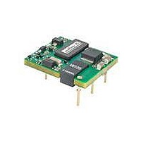
... PRODUCT OVERVIEW Featuring a full 25 Watt output in one square inch of board area, the UEI25 series isolated DC/DC converter family offers effi cient regulated DC power for printed circuit board mounting. The 0.96" x 1.1" x 0.32" (24.4 x 27.9 x 8.1 mm) converter accepts a 2:1 input voltage range Volts DC, ideal for telecom equipment. The industry-standard pin- out fi ...
Page 2
... L1 = 0.110˝ (2.79mm 0.145˝ (3.68mm)* Note: Some model number combinations may not be available. Contact Murata Power Solutions. *Alternate pin lengths may require quantity order. email: sales@murata-ps.com 07 Apr 2011 MDC_UEI25W.A03 Page Package, C75 Case (mm) Pinout 24.4x27.9x8.1 P85 24.4x27.9x8.1 P85 24.4x27.9x8.1 P85 ...
Page 3
... FUNCTIONAL SPECIFICATIONS – MODEL UEI25-033-D48 ABSOLUTE MAXIMUM RATINGS Input Voltage, Continuous Input Voltage, Transient Isolation Voltage Input Reverse Polarity On/Off Remote Control Output Power Output Current Current-limited, no damage, short-circuit protected Storage Temperature Range Absolute maximums are stress ratings. Exposure of devices to greater than any of these conditions may adversely affect long-term reliability. Proper operation under conditions other than those listed in the Performance/Functional Specifi ...
Page 4
... FUNCTIONAL SPECIFICATIONS (CONT.) – MODEL UEI25-033-D48 OUTPUT Total Output Power Voltage Nominal Output Voltage Setting Accuracy Output Voltage Range Overvoltage Protection Current Output Current Range ➂ Minimum Load Current Limit Inception Short Circuit Short Circuit Current Short Circuit Duration (remove short for ...
Page 5
... FUNCTIONAL SPECIFICATIONS – MODEL UEI25-050-D48 ABSOLUTE MAXIMUM RATINGS Input Voltage, Continuous Input Voltage, Transient Isolation Voltage Input Reverse Polarity On/Off Remote Control Output Power Output Current Current-limited, no damage, short-circuit protected Storage Temperature Range Absolute maximums are stress ratings. Exposure of devices to greater than any of these conditions may adversely affect long-term reliability. Proper operation under conditions other than those listed in the Performance/Functional Specifi ...
Page 6
... FUNCTIONAL SPECIFICATIONS (CONT.) – MODEL UEI25-050-D48 OUTPUT Total Output Power Voltage Nominal Output Voltage Setting Accuracy Output Voltage Range Overvoltage Protection Current Output Current Range ➂ Minimum Load Current Limit Inception Short Circuit Short Circuit Current Short Circuit Duration (remove short for ...
Page 7
... FUNCTIONAL SPECIFICATIONS – MODEL UEI25-120-D48 ABSOLUTE MAXIMUM RATINGS Input Voltage, Continuous Input Voltage, Transient Isolation Voltage Input Reverse Polarity On/Off Remote Control Output Power Output Current Current-limited, no damage, short-circuit protected Storage Temperature Range Absolute maximums are stress ratings. Exposure of devices to greater than any of these conditions may adversely affect long-term reliability. Proper operation under conditions other than those listed in the Performance/Functional Specifi ...
Page 8
... FUNCTIONAL SPECIFICATIONS (CONT.) – MODEL UEI25-120-D48 OUTPUT Total Output Power Voltage Nominal Output Voltage Setting Accuracy Output Voltage Range Overvoltage Protection Current Output Current Range ➂ Minimum Load Current Limit Inception Short Circuit Hiccup technique, autorecovery within ±1.25% Short Circuit Current ...
Page 9
... FUNCTION, not the pin number when laying out your PC board. END VIEW 0.475 [12.07] REF C L 6.3 0.25 Standard pin length is shown. Please refer to the Ordering Guide for alternate pin lengths. email: sales@murata-ps.com 07 Apr 2011 MDC_UEI25W.A03 Page ...
Page 10
... Anti-static foam Label Each tray units (30 units per tray) 18.0 5x 38.1 190.5 Ref A 9.5 [.38 in] Pocket Depth www.murata-ps.com UEI25 Series Single Output Isolated 25-Watt DC/DC Converters 252.0 252.0 Ref Ref 9.5 deep 19.1 Ref Ref email: sales@murata-ps.com 07 Apr 2011 MDC_UEI25W.A03 Page Label ...
Page 11
... These converters are plug-compatible to competitive units. In case of pinout numbering inconsistency, follow the pin FUNCTION, not the pin number when laying out your PC board. END VIEW 0.34 [8.64] MAX C L 0.093 [2.4] 0.13 [3.3] REF email: sales@murata-ps.com 07 Apr 2011 MDC_UEI25W.A03 Page ...
Page 12
... Nozzle Pick & 2.00 Place Location 0.079 Feed (unwind) direction Cover Tape email: sales@murata-ps.com 07 Apr 2011 MDC_UEI25W.A03 Page Function P85 Positive Vin Negative Vin Positive Vout Output Trim Negative Vout On/Off Control* 9.27 0.365 ...
Page 13
... Single Output Isolated 25-Watt DC/DC Converters Maximum Current Temperature Derating @sea level (airfl from input to output 400 LFM Vin = 36V, 48V and 60V 200 to 400 LFM Vin = bient Temperature (°C) ScopeBW=20Mhz) Trace 1= Enable. Trace 4=Vout email: sales@murata-ps.com 07 Apr 2011 MDC_UEI25W.A03 Page LFM 100 LFM 0 = 75V ...
Page 14
... Step Load Transient Response (Vin=48V, Vout=nom., Iout=50-75-50% of full load, Cload= 1 uFb ceramic || 10uF tantalum, Ta=+25°C., ScopeBW=20Mhz) Output Ripple and Noise (Vin=48V, Vout=nom., Iout=.7575mA, Cload= 1 uFb ceramic || 10uF tantalum, Ta=+25°C., ScopeBW=20Mhz) www.murata-ps.com UEI25 Series email: sales@murata-ps.com 07 Apr 2011 MDC_UEI25W.A03 Page ...
Page 15
... UEI25 Series Single Output Isolated 25-Watt DC/DC Converters Power Dissipation vs. Load Current @ 25°C Vin = 36V Vin = 48V Vin = 60V Vin = 75V 1.4 1.8 2.2 2.6 3.0 3.4 3.8 Load Current ( mps email: sales@murata-ps.com 07 Apr 2011 MDC_UEI25W.A03 Page 4.2 4.6 5.0 ...
Page 16
... Step Load Transient Response (Vin=48V, Vout=nom., Iout=50-75-50% of full load, Cload=1 μF ceramic || 10μF tantalum, Ta=+25°C., ScopeBW=20MHz) Output Ripple and Noise (Vin=48V, Vout=nom., Iout=5A, Cload=1 μF ceramic || 10μF tantalum, Ta=+25°C., ScopeBW=20MHz) www.murata-ps.com UEI25 Series email: sales@murata-ps.com 07 Apr 2011 MDC_UEI25W.A03 Page ...
Page 17
... Vin = 36V Vin = 48V Vin = 60V Vin = 75V 0.8 0.9 1.1 1.3 1.4 1.6 1.8 Load Current ( mps 48V, airfl from pin 1 to pin LFM 100 LFM 200 LFM bient temperature (°C) email: sales@murata-ps.com 07 Apr 2011 MDC_UEI25W.A03 Page 1.9 2.1 85 ...
Page 18
... ScopeBW=20Mhz) Trace 1= Enable. Trace 4=Vout 80 85 On/Off ENABLE DELAY (Vin=48, Vout=nom, Iout=2.1A, Cload=2000uF, Ta=+25°C., ScopeBW=20Mhz) Trace 1= Enable. Trace 4=Vout Output Ripple and Noise (Vin=48V, Iout = 2.1A, Cout = 1&10μ +25°C, www.murata-ps.com UEI25 Series Scope BW = 20MHz) email: sales@murata-ps.com 07 Apr 2011 MDC_UEI25W.A03 Page ...
Page 19
... Otherwise the converter may be damaged. Designers will normally use the negative output (-Output) as www.murata-ps.com UEI25 Series may vary according to the specifi c converter model. BUS CURRENT PROBE 1 +INPUT L BUS C C BUS IN 2 −INPUT Figure 2. Measuring Input Ripple Current email: sales@murata-ps.com 07 Apr 2011 MDC_UEI25W.A03 Page ...
Page 20
... Keep leads short. If the trim function is not used, leave the trim unconnected. With no trim, the converter will exhibit its specifi ed output voltage accuracy. There are two CAUTIONs to observe for the Trim input: www.murata-ps.com UEI25 Series Single Output Isolated 25-Watt DC/DC Converters email: sales@murata-ps.com 07 Apr 2011 MDC_UEI25W.A03 Page ...
Page 21
... Single Output Isolated 25-Watt DC/DC Converters +OUTPUT −INPUT ON/OFF TRIM CONTROL R TRIM DOWN +INPUT −OUTPUT +OUTPUT −INPUT ON/OFF TRIM CONTROL R TRIM UP +INPUT −OUTPUT +VCC ON/OFF CONTROL -INPUT Figure 6. Driving the On/Off Control Pin (suggested circuit) email: sales@murata-ps.com 07 Apr 2011 MDC_UEI25W.A03 Page LOAD LOAD ...
Page 22
... UEI25 Series Single Output Isolated 25-Watt DC/DC Converters QP 1.0 full load, for UEI25-050-D48NM-C QP 1.0 B, full load, for UEI25-050-D48NM-C QP 1.0 full load, for UEI25-120-D48P-C Application Note for further discussion. email: sales@murata-ps.com 07 Apr 2011 MDC_UEI25W.A03 Page 10.0 30.0 MHz Average 10.0 30 ...
Page 23
... The descriptions contained herein do not imply the granting of licenses to make, use, or sell equipment constructed in accordance therewith. Specifi cations are subject to change without notice. www.murata-ps.com/locations UEI25 Series © 2011 Murata Power Solutions, Inc. email: sales@murata-ps.com 07 Apr 2011 MDC_UEI25W.A03 Page ...