VPOL5A-5-SMT CUI Inc, VPOL5A-5-SMT Datasheet - Page 6
VPOL5A-5-SMT
Manufacturer Part Number
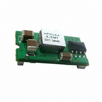
VPOL5A-5-SMT
Description
CONVERTER DC/DC 3.63V OUT 5A SMD
Manufacturer
CUI Inc
Series
V-Infinity VPOL5Ar
Type
Point of Load (POL) Non-Isolatedr
Datasheet
1.VPOL5A-5-SMT.pdf
(11 pages)
Specifications of VPOL5A-5-SMT
Output
0.75 ~ 3.63V
Number Of Outputs
1
Power (watts)
18W
Mounting Type
Surface Mount
Voltage - Input
3 ~ 5.5V
Package / Case
5-DIP SMD Module
1st Output
0.75 ~ 3.63 VDC @ 5A
Size / Dimension
0.80" L x 0.45" W x 0.24" H (20.3mm x 11.4mm x 6.1mm)
Power (watts) - Rated
18W
Operating Temperature
-40°C ~ 85°C
Efficiency
94%
Approvals
EN, IEC, UL
Lead Free Status / RoHS Status
Lead free / RoHS Compliant
3rd Output
-
2nd Output
-
Other names
102-1288-2


PART NUMBER: VPOL5A-5-SMT
20050 SW 112
Figure 3. Positive Remote On/Off Input Drive Circuit
5.7 UVLO (Under-Voltage Lockout)
The voltage on the Vcc pin determines the start of the operation of the
Converter. When the input Vcc rises and exceeds about 2.0V the
converter initiates a soft start. The UVLO function in the converter has a
hysteresis (about 100mV) built in to provide noise immunity at start-up.
6. Safety
6.1 Input Fusing and Safety Considerations.
Agency Approvals: The power Supply shall be submitted to and receive
formal approval from the following test agencies.
1.The power supply shall be approved by a nationally recognized testing
laboratory to UL/CSA 60950 3
(International)
2. CB Certificate from an internationally recognized test house in
accordance with EN 60950.
The VPOL5A-5-SMT series converters do not have an internal fuse.
However, to achieve maximum safety and system protection, always
use an input line fuse. The safety agencies require a time-delay fuse
with a maximum rating of 10A.
7. Applications
7.1 Layout Design Challenges.
In optimizing thermal design the PCB is utilized as a heat sink. Also
some heat is transferred from the SMT module to the main board through
connecting pins. The system designer or the end user must ensure that
other components and metal in the vicinity of the
VPOL5A-5-SMT series meet the spacing requirements to which the
system is approved.
Low resistance and low inductance PCB layout traces are the norm and
should be used where possible. Due consideration must also be given to
ON/OFF
Control
ON/OFF
Control
Figure 4. Negative Remote On/Off Input Drive Circuit
th
Ave. Tualatin, Oregon 97062
Q1
Q1
+Vin
Remote ON/OFF
Common
rd
+Vin
Remote ON/OFF
Common
Edition (North America) and EN60950
VPOL5A-5-SMT
VPOL5A-5-SMT
Common
Common
+Vo
+Vo
phone
phone 503.612.2300 fax
DESCRIPTION: point of load converter
proper low impedance tracks between power module, input and output
grounds. The recommended SMT footprint as shown as figure 5.
Figure 5. Recommended SMT Footprint (Top View)
0.340
(8.64)
0.06
(1.5)
Recommended Pad Layout
Dimensions are in Inches ( millimetes )
0.05
(1.3)
fax 503.612.2383
0.180
(4.57)
ON/OFF
PAD SIZE
MIN : 0.120" x 0.095 "
MAX : 0.135" x 0.110 "
VOUT
0.160
(4.06)
(17.53)
TRIM
0.690
(4.06)
0.160
(0.25)
0.010
GND
VIN
0.190
(4.83)
www.v-infinity.com
rev.
page
date
(8.89)
0.350
09/2010
6 of 11
Related parts for VPOL5A-5-SMT
Image
Part Number
Description
Manufacturer
Datasheet
Request
R

Part Number:
Description:
CONVERTER DC/DC 3.63V OUT 5A SIP
Manufacturer:
CUI Inc
Datasheet:

Part Number:
Description:
CONVERTER DC/DC 5.0V OUT 5A SMD
Manufacturer:
CUI Inc
Datasheet:

Part Number:
Description:
CONVERTER DC/DC 5.0V OUT 5A SIP
Manufacturer:
CUI Inc
Datasheet:

Part Number:
Description:
CABLE ASSY LATCH 5PIN 5X22AWG 1'
Manufacturer:
CUI Inc
Datasheet:

Part Number:
Description:
CABLE ASSY LATCH 5PIN 5X22AWG 1'
Manufacturer:
CUI Inc
Datasheet:

Part Number:
Description:
CABLE SHLD LATCH 5PIN 24AWG 6'
Manufacturer:
CUI Inc
Datasheet:

Part Number:
Description:
LINE DRIVER CABLE FOR AMT-102 1M
Manufacturer:
CUI Inc
Datasheet:

Part Number:
Description:
LINE DRIVER CABLE FOR AMT-103 1M
Manufacturer:
CUI Inc
Datasheet:

Part Number:
Description:
CABLE SHLD MATING 5PIN 24AWG 6'
Manufacturer:
CUI Inc
Datasheet:

Part Number:
Description:
CABLE ASSY LATCH 5PIN 5X24AWG 6'
Manufacturer:
CUI Inc
Datasheet:

Part Number:
Description:
SPEAKER ALNICO 8OHM 2W 100MM SQR
Manufacturer:
CUI Inc
Datasheet:

Part Number:
Description:
ac-dc converter
Manufacturer:
CUI [CUI INC]
Datasheet:
Part Number:
Description:
MEDICAL SWITCHING POWER SUPPLY
Manufacturer:
CUI [CUI INC]
Datasheet:
Part Number:
Description:
DC-DC Converter
Manufacturer:
CUI [CUI INC]
Datasheet:
Part Number:
Description:
DC/DC Converter
Manufacturer:
CUI [CUI INC]
Datasheet: