VPOL5A-5-SIP CUI Inc, VPOL5A-5-SIP Datasheet - Page 10
VPOL5A-5-SIP
Manufacturer Part Number
VPOL5A-5-SIP
Description
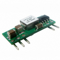
CONVERTER DC/DC 3.63V OUT 5A SIP
Manufacturer
CUI Inc
Series
V-Infinity VPOL5Ar
Type
Point of Load (POL) Non-Isolatedr
Datasheet
1.VPOL5A-5-SIP.pdf
(10 pages)
Specifications of VPOL5A-5-SIP
Output
0.75 ~ 3.63V
Number Of Outputs
1
Power (watts)
18W
Mounting Type
Through Hole
Voltage - Input
3 ~ 5.5V
Package / Case
5-SIP Module
1st Output
0.75 ~ 3.63 VDC @ 5A
Size / Dimension
0.90" L x 0.22" W x 0.40" H (22.9mm x 5.6mm x 10.2mm)
Power (watts) - Rated
18W
Operating Temperature
-40°C ~ 85°C
Efficiency
94%
Approvals
EN, IEC, UL
Lead Free Status / RoHS Status
Lead free / RoHS Compliant
3rd Output
-
2nd Output
-
Other names
102-1287


PART NUMBER: VPOL5A-5-SIP
7.8 VPOL5A-5-SIP Series Output Voltage Adustment.
The output Voltage of the VPOL5A-5-SIPS33A can be adjusted in the
range 0.75V to 3.63V by connecting a single resistor on the
motherboard (shown as Rtrim) in Figure 12v. Whe n Trim resistor is not
connected the output voltage defaults to 0.75V
The value of Rtrim-up defined as:
Where: Rtrim-up is the external resistor in ohm,
To give an exa mple of the above calculation, to set a voltage of 3.3
Vdc, Rtrim is given by:
Rtrim = 3153 ohm
For various output values various resistors are calculated and provided
in Table 3 for co nvenience.
20050 SW 112
Vo is the desired output voltage
+Vin
Common
Figure 12. Trim-up Voltage Setup
VPOL5A-5-SIP
Rtrim
Rtrim
Table 3 – Trim Resistor Values
Vo,set (V)
=
=
th
1.20
1.50
1.80
0.75
2.00
3.30
3.63
2.50
(
(
Ave. Tualatin, Oregon 97062
Vo
Common
Vo
21070
21070
_
_
+Vo
Trim
. 0
. 0
75
75
41.71
22.98
14.96
Open
11.75
6.93
3.15
2.20
Rtrim (Kohm)
_
_
5110
5110
R trim-up
)
)
R-Load
phone
phone 503.612.2300 fax
DESCRIPTION: point of load converter
0.14(3.6)
0.100(2.54)
0.700(17.78)
0.200(5.08)
0.800(20.32)
7.9 Output Ripple and Noise Measurement
The test set-up for noise and ripple measurements is shown in Figure
18. a coaxial cable with a 50ohm termination was used to prevent
impedance mismatch reflections disturbing the noise readings at
higher frequencies5^
7.10 Output Capacitance
V-Infinity’s VPOL5A-5-SIP series converters provide unconditional
stability with or without external capacitors. For good transient
response low ESR output capacitors should be located close to the
point of load.
For high current applications point has already been made in layout
considerations for low resistance and low inductance tracks.
Output capacitors with its associated ESR values have an impact on
loop stability and bandwidth. V-Infinity’s converters are designed to
work with load capacitance up-to 3,000 μF. It is rec ommended that any
additional capacitance, Maximum 3,000 μF and low ESR, be
connected close to the point of load and outside the remote
compensation point.
8. Mechanical Outline Diagrams
8.1 SIP/SMT05 Mechanical Outline Diagrams
Dimensions are in millimeters and inches
Tolerance: x.xx ±0.02 in. (0.5mm) , x.xxx ±0.010 in. (0.25 mm) unless
otherwise noted
SIZE SIP05
Figure 13. Output Voltage Ripple and Noise Measurement Set-Up
Figure 14 VPOL5A-5-SIP Mechanical Outline Diagram
1 2 3
+Vin
Common
VPOL5A-5-SIP
0.90(22.9)
fax 503.612.2382
Common
4 5
+Vo
0.025(0.64)
0.400(10.16)
0.22(5.6)Max.
0.19(4.7)
0.025(0.64)
10uF
Tant.
Ceramic
Pin
4
1
2
3
5
1uF
PIN CONNECTION
rev.
page
date
FUNCTION
+Output
Trim
Common
+V Input
On/Off
Test Jack
R-Load
08/2007
10 of 10
Related parts for VPOL5A-5-SIP
Image
Part Number
Description
Manufacturer
Datasheet
Request
R

Part Number:
Description:
CONVERTER DC/DC 3.63V OUT 5A SMD
Manufacturer:
CUI Inc
Datasheet:

Part Number:
Description:
CONVERTER DC/DC 5.0V OUT 5A SMD
Manufacturer:
CUI Inc
Datasheet:

Part Number:
Description:
CONVERTER DC/DC 5.0V OUT 5A SIP
Manufacturer:
CUI Inc
Datasheet:

Part Number:
Description:
CABLE ASSY LATCH 5PIN 5X22AWG 1'
Manufacturer:
CUI Inc
Datasheet:

Part Number:
Description:
CABLE ASSY LATCH 5PIN 5X22AWG 1'
Manufacturer:
CUI Inc
Datasheet:

Part Number:
Description:
CABLE SHLD LATCH 5PIN 24AWG 6'
Manufacturer:
CUI Inc
Datasheet:

Part Number:
Description:
LINE DRIVER CABLE FOR AMT-102 1M
Manufacturer:
CUI Inc
Datasheet:

Part Number:
Description:
LINE DRIVER CABLE FOR AMT-103 1M
Manufacturer:
CUI Inc
Datasheet:

Part Number:
Description:
CABLE SHLD MATING 5PIN 24AWG 6'
Manufacturer:
CUI Inc
Datasheet:

Part Number:
Description:
CABLE ASSY LATCH 5PIN 5X24AWG 6'
Manufacturer:
CUI Inc
Datasheet:

Part Number:
Description:
SPEAKER ALNICO 8OHM 2W 100MM SQR
Manufacturer:
CUI Inc
Datasheet:

Part Number:
Description:
ac-dc converter
Manufacturer:
CUI [CUI INC]
Datasheet:
Part Number:
Description:
MEDICAL SWITCHING POWER SUPPLY
Manufacturer:
CUI [CUI INC]
Datasheet:
Part Number:
Description:
DC-DC Converter
Manufacturer:
CUI [CUI INC]
Datasheet:
Part Number:
Description:
DC/DC Converter
Manufacturer:
CUI [CUI INC]
Datasheet: