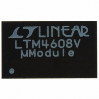
LTM4608IV#PBF Linear Technology, LTM4608IV#PBF Datasheet - Page 8

LTM4608IV#PBF
Manufacturer Part Number
LTM4608IV#PBF
Description
IC DC/DC UMODULE 8A 68-LGA
Manufacturer
Linear Technology
Series
µModuler
Type
Point of Load (POL) Non-Isolatedr
Datasheet
1.LTM4608IVPBF.pdf
(26 pages)
Specifications of LTM4608IV#PBF
Design Resources
LTM4608 Spice Model
Output
0.6 ~ 5 V
Number Of Outputs
1
Power (watts)
40W
Mounting Type
Surface Mount
Voltage - Input
2.7 ~ 5.5 V
Package / Case
68-LGA
1st Output
0.6 ~ 5 VDC @ 8A
Size / Dimension
0.59" L x 0.35" W x 0.11" H (15mm x 9mm x 2.8mm)
Power (watts) - Rated
40W
Operating Temperature
-40°C ~ 85°C
Efficiency
95%
Lead Free Status / RoHS Status
Lead free / RoHS Compliant
3rd Output
-
2nd Output
-
Available stocks
Company
Part Number
Manufacturer
Quantity
Price
LTM4608
FB (E7): The Negative Input of the Error Amplifier. Internally,
this pin is connected to V
Different output voltages can be programmed with an ad-
ditional resistor between FB and GND pins. In PolyPhase
operation, tie FB pins together for parallel operation. See
the Applications Information section for details.
I
Compensation Point. The current comparator threshold
increases with this control voltage. Tie together in parallel
operation.
I
Amplifier. Tie this pin to SGND for single phase operation.
For PolyPhase operation, tie the master’s I
while connecting all of the I
PIN FUNCTIONS
8
TH
THM
(F6): Current Control Threshold and Error Amplifier
(F5): Negative Input to the Internal I
OUT
THM
with a 10k precision resistor.
pins together.
TH
THM
Differential
to SGND
®
PGOOD (C7): Output Voltage Power Good Indicator.
Open-drain logic output that is pulled to ground when the
output voltage is not within ±10% of the regulation point.
Disabled during margining.
RUN (F1): Run Control Pin. A voltage above 1.5V will turn
on the module.
SW (C3-C5): Switching Node of the Circuit is Used for
Testing Purposes. This can be connected to an electri-
cally open circuit copper pad on the board for improved
thermal performance.
CLKOUT (F2): Output Clock Signal for PolyPhase Opera-
tion. The phase of CLKOUT is determined by the state of
the PHMODE pin.
4608fc


