LTM4619EV#PBF Linear Technology, LTM4619EV#PBF Datasheet - Page 6
LTM4619EV#PBF
Manufacturer Part Number
LTM4619EV#PBF
Description
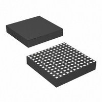
IC SWIT REG BUCK 4A ADJ 144LGA
Manufacturer
Linear Technology
Series
µModuler
Type
Point of Load (POL) Non-Isolatedr
Datasheet
1.LTM4619EVPBF.pdf
(24 pages)
Specifications of LTM4619EV#PBF
Design Resources
LTM4619 Spice Model
Output
0.8 ~ 5 V
Number Of Outputs
2
Power (watts)
30W
Mounting Type
Surface Mount
Voltage - Input
4.5 ~ 26.5 V
Package / Case
144-LGA
1st Output
0.8 ~ 5 VDC @ 4A
2nd Output
0.8 ~ 5 VDC @ 4A
Size / Dimension
0.59" L x 0.59" W x 0.11" H (15mm x 15mm x 2.8mm)
Power (watts) - Rated
30W
Operating Temperature
-40°C ~ 125°C
Lead Free Status / RoHS Status
Lead free / RoHS Compliant
3rd Output
-
Available stocks
Company
Part Number
Manufacturer
Quantity
Price


LTM4619
pin FuncTions
V
L8 to L12, M1 to M12): Power Input Pins. Apply input
voltage between these pins and PGND pins. Recommend
placing input decoupling capacitance directly between V
pins and PGND pins. For V
together.
V
D1, A2 to D2, A3 to D3): Power Output Pins. Apply output
load between these pins and PGND pins. Recommend
placing output decoupling capacitance directly between
these pins and PGND pins.
PGND (H1, H2, H4, H9, H11, H12, G1 to G12, F1 to F5,
F7 to F12, E1 to E12, D4 to D9, C4 to C9, B4 to B9, A4 to
A9): Power ground pins for both input and output returns.
INTV
additional decoupling of the 5V internal regulator.
EXTV
EXTV
disabled and external power supplies current to reduce
the power dissipation in the module. This will improve the
efficiency more at high input voltages.
SGND (J6, J7, H6, H7): Signal Ground Pin. Return ground
path for all analog and low power circuitry. Tie a single
connection to PGND in the application.
MODE/PLLIN (H8): Mode selection or external synchroniza-
tion pin. Tying this pin high enables pulse-skipping mode.
Tying this pin low enables force continuous operation.
Floating this pin enables Burst Mode operation. A clock
on the pin will force the controller into the continuous
mode of operation and synchronize the internal oscillator.
The suitable synchronizable frequency range is 250kHz to
780kHz subject to inductor ripple current limits described
in the FREQ/PLLFLTR pin section. The external clock input
high threshold is 1.6V, while the input low threshold is 1V.
FREQ/PLLFLTR (J8): Frequency Selection Pin. An internal
lowpass filter is tied to this pin. The frequency can be
selected from 250kHz to 780kHz by varying the DC volt-
age on this pin from 0V to 2.4V. The nominal frequency
6
IN
OUT1
(J1 to J3, J10 to J12, K1 to K4, K9 to K12, L1 to L5,
CC
CC
CC
, V
(F6): Internal 5V Regulator Output. This pin is for
(J4): External Power Input to Controller. When
is higher than 4.7V, the internal 5V regulator is
OUT2
(A10 to D10, A11 to D11, A12 to D12, A1 to
IN
< 5.5, tie V
IN
and INTV
CC
IN
setting is 500kHz. Frequency selection can be modified as
long as the inductor ripple current is less ≈40% to 50%
at the output current
Where FREQ is selected operating frequency and L is
the inductor value. Leave this pin floating when external
synchronization is used.
TK/SS1, TK/SS2 (K8, K5): Output Voltage Tracking and
Soft-Start Pins. Internal soft-start currents of 1.3µA charge
the soft-start capacitors. See the Applications Information
section to use the tracking function.
V
amplifier. Internally, this pin is connected to V
a 60.4k precision resistor. Different output voltages can
be programmed with an additional resistor between V
and SGND pins. See the Applications Information section
for details.
COMP1, COMP2 (L7, L6): Current Control Threshold and
Error Amplifier Compensation Point. The module has been
internally compensated for most I/O ranges.
PGOOD (H5): Output Voltage Power Good Indicator. Open
drain logic output that is pulled to ground when the output
voltage is not within ±7.5% of the regulation point.
RUN1, RUN2 (J9, J5): Run Control Pins. 0.5µA pull-up
currents on these pins turn on the module if these pins
are floating. Forcing either of these pins below 1.2V will
shut down the corresponding outputs. An additional 4.5µA
pull-up current is added to this pin, once the RUN pin rises
above 1.2V. Also, active control or pull-up resistors can
be used to enable the RUN pin. The maximum voltage is
6V on these pins.
SW1, SW2 (H10, H3): Switching Test Pins. These pins
are provided externally to check the operation frequency.
FB1
I
RIPPLE
, V
FB2
=
(K7, K6): The negative input of the error
FREQ
1
1–
L
V
V
OUT
IN
V
OUT
OUT
with
4619fa
FB
Related parts for LTM4619EV#PBF
Image
Part Number
Description
Manufacturer
Datasheet
Request
R

Part Number:
Description:
Dual, 26vin, 4a Dc/dc ?module Regulator
Manufacturer:
Linear Technology Corporation
Datasheet:

Part Number:
Description:
IC SWIT REG BUCK 4A ADJ 144LGA
Manufacturer:
Linear Technology
Datasheet:

Part Number:
Description:
CD ROM LINEARVIEW DATASHEETS
Manufacturer:
Linear Technology
Part Number:
Description:
Standalone Linear Li-Ion Battery Charger with Thermal Regulation in ThinSOT
Manufacturer:
Linear Technology Corporation
Datasheet:
Part Number:
Description:
Low noise, high frequency, 8th order linear phase lowpass filter
Manufacturer:
Linear Technology Corporation
Datasheet:
Part Number:
Description:
Manufacturer:
Linear Technology Corporation
Datasheet:
Part Number:
Description:
Manufacturer:
Linear Technology Corporation
Datasheet:
Part Number:
Description:
Manufacturer:
Linear Technology Corporation
Datasheet:
Part Number:
Description:
Manufacturer:
Linear Technology Corporation
Datasheet:
Part Number:
Description:
Manufacturer:
Linear Technology Corporation
Datasheet:
Part Number:
Description:
Manufacturer:
Linear Technology Corporation
Datasheet:
Part Number:
Description:
Manufacturer:
Linear Technology Corporation
Datasheet:
Part Number:
Description:
Dual and Quad, JFET Input Precision High Speed Op Amps
Manufacturer:
Linear Technology Corporation
Datasheet:
Part Number:
Description:
Manufacturer:
Linear Technology Corporation
Datasheet:
Part Number:
Description:
1, 2, 6 and 8 Channel, 10-Bit Serial I/O Data Acquisition Systems
Manufacturer:
Linear Technology Corporation
Datasheet: