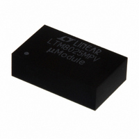
LTM8025MPV#PBF Linear Technology, LTM8025MPV#PBF Datasheet - Page 13

LTM8025MPV#PBF
Manufacturer Part Number
LTM8025MPV#PBF
Description
IC CONVERTER BUCK 3A ADJ 70LGA
Manufacturer
Linear Technology
Series
µModuler
Type
Point of Load (POL) Non-Isolatedr
Datasheet
1.LTM8025EVPBF.pdf
(20 pages)
Specifications of LTM8025MPV#PBF
Design Resources
LTM8025 Spice Model
Output
0.8 ~ 24 V
Number Of Outputs
1
Power (watts)
72W
Mounting Type
Surface Mount
Voltage - Input
3.6 ~ 36 V
Package / Case
70-LGA
1st Output
0.8 ~ 24 VDC @ 3A
Size / Dimension
0.59" L x 0.35" W x 0.17" H (15mm x 9mm x 4.32mm)
Power (watts) - Rated
72W
Operating Temperature
-55°C ~ 125°C
Lead Free Status / RoHS Status
Lead free / RoHS Compliant
3rd Output
-
2nd Output
-
Available stocks
Company
Part Number
Manufacturer
Quantity
Price
APPLICATIONS INFORMATION
on is higher than that required to run, and depends upon
whether the RUN/SS is used. As shown in the Typical
Performance Characteristics section, the minimum input
voltage to run a 3.3V output at light load is only about 3.6V,
but, if the RUN/SS is pulled up to V
start. If the LTM8025 is enabled with the RUN/SS pin, the
minimum voltage to start at light loads is lower, about 4.3V.
Similar curves detailing this behavior of the LTM8025 for
other outputs are also included in the Typical Performance
Characteristics section.
Soft-Start
The RUN/SS pin can be used to soft-start the LTM8025,
reducing the maximum input current during start-up. The
RUN/SS pin is driven through an external RC fi lter to cre-
ate a voltage ramp at this pin. Figure 1 shows the start-up
and shutdown waveforms with the soft-start circuit. By
choosing an appropriate RC time constant, the peak start-
up current can be reduced to the current that is required to
regulate the output, with no overshoot. Choose the value
of the resistor so that it can supply at least 20μA when
the RUN/SS pin reaches 2.5V.
0.22μF
Frequency Foldback
The LTM8025 is equipped with frequency foldback which
acts to reduce the thermal and energy stress on the internal
power elements during a short circuit or output overload
condition. If the LTM8025 detects that the output has fallen
out of regulation, the switching frequency is reduced as a
function of how far the output is below the target voltage.
This in turn limits the amount of energy that can be delivered
15k
Figure 1. To Soft-Start the LTM8025, Add a Resistor and
Capacitor to the RUN/SS Pin
RUN
RUN/SS
RUN
2ms/DIV
IN
, it takes 5.5V
8025 F01
I
1A/DIV
V
2V/DIV
V
2V/DIV
IN
L
RUN/SS
OUT
to
to the load under fault. During the start-up time, frequency
foldback is also active to limit the energy delivered to the
potentially large output capacitance of the load.
Synchronization
The internal oscillator of the LTM8025 can be synchronized
by applying an external 250kHz to 2MHz clock to the SYNC
pin. Do not leave this pin fl oating. When synchronizing
the LTM8025, select an R
to an operating frequency 20% lower than the intended
synchronization frequency (see the Frequency Selection
section).
In addition to synchronization, the SYNC pin controls Burst
Mode behavior. If the SYNC pin is driven by an external
clock, or pulled up above 0.7V, the LTM8025 will not en-
ter Burst Mode operation, but will instead skip pulses to
maintain regulation instead.
Shorted Input Protection
Care needs to be taken in systems where the output will be
held high when the input to the LTM8025 is absent. This
may occur in battery charging applications or in battery
backup systems where a battery or some other supply is
diode ORed with the LTM8025’s output. If the V
allowed to fl oat and the SHDN pin is held high (either by a
logic signal or because it is tied to V
internal circuitry will pull its quiescent current through
its internal power switch. This is fi ne if your system can
tolerate a few milliamps in this state. If you ground the
RUN/SS pin, the input current will drop to essentially zero.
However, if the V
held high, then parasitic diodes inside the LTM8025 can
pull large currents from the output through the V
Figure 2 shows a circuit that will run only when the input
voltage is present and that protects against a shorted or
reversed input.
PCB Layout
Most of the headaches associated with PCB layout have
been alleviated or even eliminated by the high level of
integration of the LTM8025. The LTM8025 is neverthe-
less a switching power supply, and care must be taken to
minimize EMI and ensure proper operation. Even with the
IN
pin is grounded while the output is
T
resistor value that corresponds
IN
), then the LTM8025’s
LTM8025
IN
13
IN
pin is
8025fa
pin.


