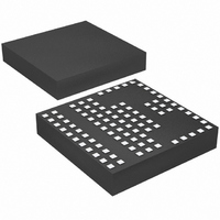
LTM4600HVEV#PBF Linear Technology, LTM4600HVEV#PBF Datasheet - Page 18

LTM4600HVEV#PBF
Manufacturer Part Number
LTM4600HVEV#PBF
Description
IC DC/DC UMODULE 10A 104-LGA
Manufacturer
Linear Technology
Series
µModuler
Type
Point of Load (POL) Non-Isolatedr
Specifications of LTM4600HVEV#PBF
Design Resources
LTM4600HV Spice Model
Output
0.6 ~ 5 V
Number Of Outputs
1
Power (watts)
50W
Mounting Type
Surface Mount
Voltage - Input
4.5 ~ 28 V
Package / Case
104-LGA
1st Output
0.6 ~ 5 VDC @ 10A
Size / Dimension
0.59" L x 0.59" W x 0.11" H (15mm x 15mm x 2.8mm)
Power (watts) - Rated
50W
Operating Temperature
-40°C ~ 85°C
Efficiency
92%
Dc To Dc Converter Type
Step Down
Pin Count
104
Input Voltage
28V
Output Voltage
0.6 to 5V
Switching Freq
850KHz
Output Current
10A
Package Type
LGA
Output Type
Adjustable
Switching Regulator
Yes
Mounting
Surface Mount
Input Voltage (min)
4.5V
Operating Temperature Classification
Industrial
Lead Free Status / RoHS Status
Lead free / RoHS Compliant
3rd Output
-
2nd Output
-
Lead Free Status / Rohs Status
Compliant
Available stocks
Company
Part Number
Manufacturer
Quantity
Price
APPLICATIO S I FOR ATIO
LTM4600HV
t
band.
Using the frequency = (I
I
calculated from 12V input was 103μA, so a resistor from
f
57μA, sets the adequate I
range for the higher duty cycle conversion of 12V to
5V. Input voltage range is limited to 9V to 16V. Higher
input voltages can be used without the 15k on f
inductor ripple current gets too high above 16V, and the
400ns minimum off-time is limited below 9V.
Equations for setting frequency for 5V to 3.3V:
18
ON
ON
ADJ
t
t
I
frequency = (I
DC = duty cycle, duty cycle is (V
t
switching period; t
ON
OFF
ON
S
and t
= (1MHz • 2.4V • 10pF) • (1/0.41) ≅ 58μA. I
to ground = (0.7V/15k) = 46μA. 103μA – 46μA =
= t
= 0.41 • 1μs ≅ 410ns
= (V
= 1μs – 410ns ≅ 590ns
OFF
ON
IN
+ t
are above the minimums with adequate guard
– 0.7V)/110k; I
OFF
, t
ON
U
ON
/[2.4V • 10pF]) • DC = 1.07MHz;
S
= on-time, t
= 1/frequency
ON
ON
5V TO 3.3V AT 8A WITH f
LTM4600HV MINIMUM ON-TIME = 100ns
LTM4600HV MINIMUM OFF-TIME = 400ns
U
/[2.4V • 10pF]) • DC, solve for
RUN/SOFT-START
C3
10μF
25V
current for proper frequency
ON
= 39μA
4.5V TO 7V
C1
10μF
25V
OUT
W
OFF
/V
= off-time of the
ADJ
IN
= 30.1k
)
EXTV
FCB
RUN/SS
COMP
CC
ON
SGND
U
V
LTM4600HV
IN
ADJ
current
. The
5V to 3.3V at 8A
PGND
f
ADJ
PGOOD
V
V
30.1k
OSET
SV
C1, C3: TDK C3216X5R1E106MT
C2: TAIYO YUDEN, JMK316BJ226ML
C4: SANYO POSCAP, 6TPE330MIL
4600 F22
OUT
R1
IN
t
~450kHz frequency or 2.22μs period is chosen for 5V to
3.3V. Frequency range is about 450kHz to 650kHz from
4.5V to 7V input.
t
band.
Using the frequency = (I
I
calculated from 5V input was 39μA, so a resistor from f
to ground = (0.7V/30.1k) = 23μA. 39μA – 23μA = 16μA,
sets the adequate I
for the higher duty cycle conversion of 5V to 3.3V. Input
voltage range is limited to 4.5V to 7V. Higher input voltages
can be used without the 30.1k on f
current gets too high above 7V, and the 400ns minimum
off-time is limited below 4.5V.
OFF
ON
ON
t
t
t
ON
ON
OFF
and t
= (450kHz • 2.4V • 10pF) • (1/0.66) ≅ 16μA. I
OPEN DRAIN
must be greater than 400ns, or t
= DC • t
= 0.66 • 2.22μs ≅ 1.46μs
= 2.22μs – 1.46μs ≅ 760ns
OFF
C5
100pF
are above the minimums with adequate guard
3.3V AT 8A
R2
22.1k
1%
S
ON
C2
22μF
EFFICIENCY = 94%
current for proper frequency range
ON
+
/[2.4V • 10pF]) • DC, solve for
C4
330μF
6.3V
ADJ
. The inductor ripple
S
– t
ON
> 400ns.
ON
current
4600hvfc
ADJ


