QBW018A0B1Z Lineage Power, QBW018A0B1Z Datasheet

CONVERTER DC/DC 12V 216W OUT T/H

QBW018A0B1Z

Manufacturer Part Number
QBW018A0B1Z
Description
CONVERTER DC/DC 12V 216W OUT T/H
Manufacturer
Lineage Power
Series
QBW018A0Br
Type
Isolated with Remote On/Offr
Datasheet

Specifications of QBW018A0B1Z

Output
12V
Number Of Outputs
1
Power (watts)
216W
Mounting Type
Through Hole
Voltage - Input
36 ~ 75V
Package / Case
7-DIP Module, 1/4 Brick
1st Output
12 VDC @ 18A
Size / Dimension
2.28" L x 1.45" W x 0.42" H (57.9mm x 36.8mm x 10.7mm)
Power (watts) - Rated
216W
Operating Temperature
-40°C ~ 85°C
Efficiency
93%
Approvals
CE, CSA, UL, VDE
Product
Isolated
Output Power
216 W
Input Voltage Range
36 V to 75 V
Input Voltage (nominal)
48 V
Output Voltage (channel 1)
12 V
Output Current (channel 1)
18 A
Isolation Voltage
1500 VDC
Package / Case Size
DIP
Output Type
Isolated
Output Voltage
12 V
Lead Free Status / RoHS Status
Lead free / RoHS Compliant
3rd Output
-
2nd Output
-
Lead Free Status / Rohs Status
 Details
Other names
108995247
555-1109
Data Sheet
January 26, 2011
Applications
Options
Description
The QBW018A0B series of dc-dc converters are an expansion of a new generation of DC/DC power modules
designed to support 12Vdc intermediate bus applications where multiple low voltages are subsequently generated
using discrete/modular point of load (POL) converters. The QBW018A0B series provide up to 18A output current in
an industry standard quarter brick, which makes it an ideal choice for small space, high current and 12V intermediate
bus voltage applications. The converter incorporates synchronous rectification technology and innovative packaging
techniques to achieve ultra high efficiency reaching 93% at 12V full load. This leads to lower power dissipation such
that for many applications a heat sink is not required.
The QBW018A0B series power modules are isolated dc-dc converters that operate over an input voltage range from
36 to 75 Vdc and provide a single regulated output. The output is fully isolated from the input, allowing versatile
polarity configurations and grounding connections. Built-in filtering for both input and output minimizes the need for
external filtering.
This product is affected by a Permanent Injunction entered by the United States District Court for the Eastern District of
Texas, Marshall Division in Civil Action No. 2:07-cv-00497-TJW-CE (copy enclosed). As set forth in that Order, certain acts
associated with this product are prohibited. This Product is Not for Sale in, Use in, or Importation into the United States.
ISO is a registered trademark of the International Organization of Standards
**
§ This product is intended for integration into end-use equipment. All of the required procedures of end-use equipment should be followed
RoHS Compliant
CSA is a registered trademark of Canadian Standards Association.
VDE is a trademark of Verband Deutscher Elektrotechniker e.V.
UL is a registered trademark of Underwriters Laboratories, Inc.
Distributed power architectures
Intermediate bus voltage applications
Telecommunications equipment
Servers and storage applications
Networking equipment
Negative Remote On/Off logic
Active load sharing (Parallel Operation)
Baseplate option (-H)
Auto restart after fault shutdown
Case ground pin
QBW018A0B Series Power Modules, DC - DC Converters:
36 – 75Vdc Input; 12Vdc Output; 18A Output Current
Features
Compliant to RoHS EU Directive 2002/95/EC (-Z
versions)
Compliant to ROHS EU Directive 2002/95/EC with
lead solder exemption (non-Z versions)
High power density: 155 W/in
High efficiency – 93% at 12V full load
Improved Thermal Performance:
12A at 70ºC at 2m/s (400LFM)
Delivers up to 18A output current
Low output ripple and noise
Industry standard Quarter brick:
57.9 mm x 36.8 mm x 10.6 mm
(2.28 in x 1.45 in x 0.42 in)
Cost efficient open frame design
Single optimal regulated output
2 : 1 input voltage range
Constant switching frequency
Positive Remote On/Off logic
Output over current/voltage protection
Overtemperature protection
Wide operating temperature range (-40°C to 85°C)
ISO* 9001 certified manufacturing facilities
Meets the voltage isolation requirements for
ETSI 300-132-2 and complies with and is licensed for
Basic Insulation rating per EN60950-1
UL** 60950-1 Recognised, CSA
03 Certified, and VDE
Licensed
CE mark meets 2006/95/EC directive
Document No: DS04-010 ver. 1.48
0805 (IEC60950, 3
PDF name: QBW018A0B.pdf
3
C22.2 No. 60950-1-
§
rd
Edition)

Related parts for QBW018A0B1Z

QBW018A0B1Z Summary of contents

Page 1

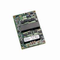
Data Sheet January 26, 2011 QBW018A0B Series Power Modules Converters: 36 – 75Vdc Input; 12Vdc Output; 18A Output Current RoHS Compliant Applications  Distributed power architectures  Intermediate bus voltage applications  Telecommunications equipment  Servers and ...

Page 2

Data Sheet January 26, 2011 Absolute Maximum Ratings Stresses in excess of the absolute maximum ratings can cause permanent damage to the device. These are absolute stress ratings only, functional operation of the device is not implied at these or ...

Page 3

January 26, 2011 (continued) Electrical Specifications Parameter Output Voltage Set-point ( =25°C) IN IN, min O O, max A Output Voltage (Over all operating input voltage, resistive load, and temperature conditions until end of ...

Page 4

January 26, 2011 Feature Specifications Unless otherwise indicated, specifications apply over all operating input voltage, resistive load, and temperature conditions. See Feature Descriptions for additional information. Parameter Remote On/Off Signal Interface ( Signal referenced to V ...

Page 5

Data Sheet January 26, 2011 Characteristic Curves The following figures provide typical characteristics for the QBW018A0B (12V, 18A) at 25ºC. The figures are identical for either positive or negative Remote On/Off logic Io=18A Io=9A ...

Page 6

Data Sheet January 26, 2011 (continued) Characteristic Curves The following figures provide typical characteristics for the QBW018A0B (12V, 18A) at 25ºC. The figures are identical for either positive or negative Remote On/Off logic. 12.3 12.2 Io=0A 12.1 Io=9A 12 11.9 ...

Page 7

Data Sheet January 26, 2011 Test Configurations Note: Measure input reflected-ripple current with a simulated source inductance (LTEST µH. Capacitor CS offsets possible battery impedance. Measure current as shown above. Figure 9. Input Reflected Ripple Current Test Setup. ...

Page 8

Data Sheet January 26, 2011 Feature Description Remote On/Off Two remote on/off options are available. Positive logic remote on/off turns the module on during a logic-high voltage on the ON/OFF pin, and off during a logic low. Negative logic remote ...

Page 9

Data Sheet January 26, 2011 Feature Description (continued) Forced Load Sharing (Parallel Operation with – P option) For additional power requirements, the power module can be configured for parallel operation with active load current sharing. Good layout techniques should be ...

Page 10

Data Sheet January 26, 2011 Thermal Considerations The power modules operate in a variety of thermal environments and sufficient cooling should be provided to help ensure reliable operation. Thermal considerations include ambient temperature, airflow, module power dissipation, and the need ...

Page 11

... For Pb solder, the recommended pot temperature is 260C, while the Pb-free solder pot 100 270C max. Not all RoHS-compliant through-hole products can be processed with paste-through-hole ( Pb-free reflow process. If additional information is needed, please consult with your Lineage Power Power System representative for more details. 11 ...

Page 12

Data Sheet January 26, 2011 Mechanical Outline for QBW018A0B Through Hole Module Dimensions are in millimeters and [inches]. Tolerances: x.x mm  0.5 mm [x.xx in.  0.02 in.] (Unless otherwise indicated) x.xx mm  0.25 mm [x.xxx in  ...

Page 13

Data Sheet January 26, 2011 Mechanical Outline for QBW018A-H (Baseplate version) Through Hole Module Dimensions are in millimeters and [inches]. Tolerances: x.x mm  0.5 mm [x.xx in.  0.02 in.] (Unless otherwise indicated) x.xx mm  0.25 mm [x.xxx ...

Page 14

Data Sheet January 26, 2011 Recommended Pad Layout Dimensions are in millimeters and (inches). Tolerances: x.x mm  0.5 mm (x.xx in.  0.02 in.) [Unless otherwise indicated] x.xx mm  0.25 mm (x.xxx in  0.010 in.) 3.6 (.14) ...

Page 15

... Through hole QBW018A0B641 93% Through hole QBW018A0B-H 93% Through hole QBW018A0B1-H 93% Through hole QBW018A0B71-BH 93% Through hole QBW018A0B641-13 93% Through hole QBW018A0BZ 93% Through hole QBW018A0B1Z 93% Through hole QBW018A0B41Z 93% Through hole QBW018A0B16Z 93% Through hole QBW018A0B641Z 93% Through hole QBW018A0B1-BZ 93% Through hole QBW018A0B-HZ 93% Through hole QBW018A0B1-HZ 93% Through hole ...

Related keywords