YNV12T10-0G POWER ONE, YNV12T10-0G Datasheet - Page 6
YNV12T10-0G
Manufacturer Part Number
YNV12T10-0G
Description
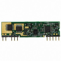
CONVERTER DC-DC 12V 10A SIP
Manufacturer
POWER ONE
Series
Yr
Type
Point of Load (POL) Non-Isolatedr
Datasheet
1.YNV12T10-0G.pdf
(25 pages)
Specifications of YNV12T10-0G
Output
0.75 ~ 5.5V
Number Of Outputs
1
Power (watts)
55W
Mounting Type
Through Hole
Voltage - Input
9.6 ~ 14V
Package / Case
10-SIP Module
1st Output
0.75 ~ 5.5 VDC @ 10A
Size / Dimension
2.00" L x 0.28" W x 0.54" H (50.8mm x 7.1mm x 13.7mm)
Power (watts) - Rated
55W
Operating Temperature
-40°C ~ 85°C
Efficiency
94%
Approvals
cUL, EN, UL
Package
10SIP
Output Current
10 A
Output Voltage
0.7525 to 5.5 V
Input Voltage
12 V
Output Power
50 W
Switching Regulator
Yes
Input Voltage Range
9.6 V to 14 V
Input Voltage (nominal)
12 V
Output Voltage (channel 1)
0.7525 V to 5.5 V
Output Current (channel 1)
10 A
Package / Case Size
SIP
Output Type
Regulated
Product
Non-Isolated / POL
Lead Free Status / RoHS Status
Lead free / RoHS Compliant
3rd Output
-
2nd Output
-
Lead Free Status / Rohs Status
Lead free / RoHS Compliant
Other names
179-2377


Because the sense lead carries minimal current,
large trace on the end-user board is not required.
However, the sense trace should be located close
to a ground plane to minimize system noise and
insure optimum performance.
When utilizing the remote sense feature, care
must be taken not to exceed the maximum
allowable output power capability of the converter,
equal to the product of the nominal output voltage
and the allowable output current for the given
conditions.
When using remote sense, the output voltage at
the converter can be increased up to 0.5V above
the nominal rating in order to maintain the required
voltage across the load. Therefore, the designer
must, if necessary, decrease the maximum current
(originally obtained from the derating curves) by
the same percentage to ensure the converter’s
actual output power remains at or below the
maximum allowable output power.
Output Voltage Programming (Pin 9)
The output voltage can be programmed from
0.7525V to 5.5V by connecting an external resistor
between the TRIM pin (Pin 9) and the GND pin
(Pin 5); see Fig. C.
A trim resistor, R
can be calculated using the following equation:
where,
MCD10202 Rev. 1.0, 24-Jun-10
R
R
V
Vin
Vin
T
TRIM
O
RIM
REQ
Fig. B: Remote sense circuit configuration.
Required value of trim resistor [k]
(V
Desired (trimmed) output voltage [V]
O
-
REQ
10
6
ON/OFF
GND
Vin
-
5 .
0.7525)
TRIM
, for a desired output voltage
Nex
(Top View)
Converter
TM
-v
9.6-14 VDC Input; 0.7525-5.5 VDC Programmable @ 10A
Series
1
SENSE
TRIM
GND
Vout
5
[k]
Rw
Rw
Rload
YNV12T10 DC-DC Converter Data Sheet
Page 6 of 25
Note that the tolerance of a trim resistor directly
affects
recommended to use standard 1% or 0.5%
resistors; for tighter tolerance, two resistors in
parallel are recommended rather than one
standard value from Table 1.
The ground pin of the trim resistor should be
connected directly to the converter GND pin (Pin
5) with no voltage drop in between. Table 1
provides the trim resistor values for popular output
voltages.
The output voltage can also be programmed by an
external voltage source. To make trimming less
sensitive, a series external resistor (Rext) is
recommended between the TRIM pin and the
programming voltage source. The control voltage
can be calculated by the formula:
where,
the voltage source; the value can be chosen
R
V
V
Vin
Fig. C: Configuration for programming output voltage.
V
CTRL
CTRL
EXT
0-REG
0.7525
1.0
1.2
1.5
1.8
2.0
2.5
3.3
5.0
5.5
External resistor between the TRIM pin and
[V]
0
Control voltage [V]
7 .
the
Table 1: Trim Resistor Value
www.power-one.com
1 (
6
R
output
ON/OFF
Vin
GND
TRIM
22.46
R
open
41.2
13.0
3.12
1.47
1.21
9.0
7.4
5.0
EXT
[kΩ]
)(V
Nex
(Top View)
Converter
voltage
TM
O
15
-v
-
REQ
Series
Standard Value [kΩ]
-
0.7525)
The Closest
SENSE
tolerance.
TRIM
GND
Vout
41.2
22.6
13.0
9.09
7.32
4.99
3.09
1.47
1.21
5
R
[V]
TRIM
It
Rload
is
Related parts for YNV12T10-0G
Image
Part Number
Description
Manufacturer
Datasheet
Request
R

Part Number:
Description:
SWITCHING POWER SUPPLIES, SINGLE OUTPUT, 80 WATTS
Manufacturer:
POWER ONE
Datasheet:
Part Number:
Description:
HAS SERIES - 30 WATT
Manufacturer:
POWER ONE
Datasheet:
Part Number:
Description:
SINGLE OUTPUT
Manufacturer:
POWER ONE
Datasheet:

Part Number:
Description:
BRS DC/DC converters(1.5 WATT)
Manufacturer:
Power-One
Datasheet:
Part Number:
Description:
3...15 Watt DC-DC Converter
Manufacturer:
Power-One
Datasheet:
Part Number:
Description:
HBS SERIES - 100 WATT
Manufacturer:
Power-One
Datasheet:
Part Number:
Description:
3...15 Watt DC-DC Converter
Manufacturer:
Power-One
Datasheet:
Part Number:
Description:
BUS DC/DC converters(3 WATT)
Manufacturer:
Power-One
Datasheet:
Part Number:
Description:
HES SERIES 150 WATT
Manufacturer:
Power-One
Datasheet:
Part Number:
Description:
1.25 WATT
Manufacturer:
Power-One
Datasheet: