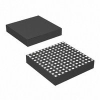
LTM4615EV#PBF Linear Technology, LTM4615EV#PBF Datasheet - Page 12

LTM4615EV#PBF
Manufacturer Part Number
LTM4615EV#PBF
Description
IC SWIT REG BUCK 4A ADJ 144LGA
Manufacturer
Linear Technology
Series
µModuler
Type
Point of Load (POL) Non-Isolatedr
Specifications of LTM4615EV#PBF
Design Resources
LTM4615 Spice Model
Output
0.8 ~ 5 V
Number Of Outputs
3
Power (watts)
12W
Mounting Type
Surface Mount
Voltage - Input
2.38 ~ 5.5 V
Package / Case
144-LGA
1st Output
0.8 ~ 5 VDC @ 4A
2nd Output
0.8 ~ 5 VDC @ 4A
3rd Output
0.8 ~ 5 VDC @ 4A
Size / Dimension
0.59" L x 0.59" W x 0.11" H (15mm x 15mm x 2.8mm)
Power (watts) - Rated
12W
Operating Temperature
-40°C ~ 125°C
Efficiency
95%
Primary Input Voltage
5.5V
No. Of Outputs
3
Output Voltage
5V
Output Current
1.5A
Voltage Regulator Case Style
LGA
No. Of Pins
144
Operating Temperature Range
-40°C To +125°C
Rohs Compliant
Yes
Lead Free Status / RoHS Status
Lead free / RoHS Compliant
Available stocks
Company
Part Number
Manufacturer
Quantity
Price
SLAVE
LTM4615
APPLICATIONS INFORMATION
Fault Conditions: Current Limit and Overcurrent
Foldback
The LTM4615 has current mode control, which inher-
ently limits the cycle-by-cycle inductor current not only
in steady-state operation, but also in transient.
Along with foldback current limiting in the event of an
overload condition, the LTM4615 has overtemperature
shutdown protection that inhibits switching operation
around 150°C for each channel.
Run Enable and Soft-Start
The RUN/SS pins provide a dual function of enable and
soft-start control for each channel. The RUN/SS pins are
used to control turn on of the LTM4615. While each enable
pin is below 0.5V, the LTM4615 will be in a low quiescent
current state. At least a 0.8V level applied to the enable
pins will turn on the LTM4615 regulators. This pin can be
used to sequence the regulator channels. The soft-start
control is provided by a 1M pull-up resistor (R
1000pF capacitor (C
each channel. An external capacitor can be applied to the
RUN/SS pin to increase the soft-start time. A typical value
is 0.01μF . The approximate equation for soft-start:
12
1.2V
22μF
6.3V
C10
4A
t
SOFTSTART
22μF
6.3V
C3
C9
22μF
6.3V
=
In
C4
22μF
6.3V
⎛
⎝ ⎜
SS
V
1.5V
) as drawn in the block diagram for
IN
R
10k
*FAIR-RITE 0805 2508056007Y6
FB1
OPTIONAL FILTER
V
– .
4.99k
IN
R
1 8
TB
V
1.2V
R
10k
TA
⎞
⎠ ⎟
•
R
L1 0.2μH*
10k
Figure 2. Dual Outputs (1.5V and 1.2V) with Tracking
R3
SS
10μF
PGOOD1
C12
•
C
SS
10μF
6.3V
C1
PGOOD1
V
FB1
COMP1
TRACK1
RUN/SS1
LDO_IN
EN3
BOOST3
OUT1
SS
GND1
V
) and a
IN1
LTM4615
GND2
V
IN
3V TO 5.5V
GND3
V
where R
Figure 1, and the 1.8V is soft-start upper range. The
soft-start function can also be used to control the output
ramp-up time, so that another regulator can be easily
tracked to it.
Output Voltage Tracking
Output voltage tracking can be programmed externally
using the TRACK pins. Either output can be tracked up
or down with another regulator. The master regulator’s
output is divided down with an external resistor divider
that is the same as the slave regulator’s feedback divider to
implement coincident tracking. The LTM4615 uses a very
accurate 4.99k resistor for the internal top feedback resistor.
Figure 2 shows an example of coincident tracking.
Equations:
LDO_OUT
IN2
RUN/SS2
PGOOD2
PGOOD3
TRACK2
COMP2
V
Slave
TRACK
OUT2
FB2
FB3
C2
10μF
6.3V
SS
R6
10k
=
1V LOW NOISE AT 1A
PGOOD2
V
1
IN
⎛
⎝ ⎜
and C
PGOOD3
1V
LOW NOISE
=
OR A CONTROL RAMP
1
+
⎛
⎝ ⎜
10k
R4
4 99
4
R
.
SS
. .
99
FB
R5
3.32k
R
1
k R
are shown in the block diagram of
k
FB
+
⎞
⎠ ⎟
1
C11
10μF
6.3V
•
TRACK
FB
1
⎞
⎠ ⎟
C13
C
SSEXT
•
Master
1
22μF
6.3V
R
5.76k
FB2
C5
22μF
6.3V
C7
C6
22μF
6.3V
4615 F02
MASTER
1.5V
4A
C8
22μF
6.3V
4615f


