S82K-01512 Omron, S82K-01512 Datasheet - Page 2
S82K-01512
Manufacturer Part Number
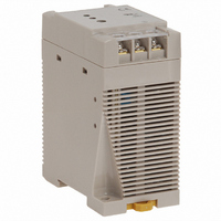
S82K-01512
Description
POWER SUPPLY SWITCH 12VDC AC-IN
Manufacturer
Omron
Series
S82Kr
Datasheet
1.S82K-00712.pdf
(15 pages)
Specifications of S82K-01512
Voltage - Output
12V
Number Of Outputs
1
Power (watts)
15W
Applications
Commercial
Power Supply Type
Switching (Closed Frame)
Voltage - Input
85 ~ 264VAC
Mounting Type
DIN Rail
1st Output
12 VDC @ 1.2A
Size / Dimension
3.58" L x 1.77" W x 2.95" H (91mm x 45mm x 75mm)
Power (watts) - Rated
15W
Operating Temperature
-10°C ~ 50°C
Efficiency
66%
Approvals
CE, CSA, cUL, cUR, UL, VDE
Lead Free Status / RoHS Status
Lead free / RoHS Compliant
3rd Output
-
2nd Output
-
4th Output
-
Other names
Q1082099
S82K-01512
S82K01512
Z2361
S82K-01512
S82K01512
Z2361


Specifications
■ Ratings/Characteristics
Note:1. When a load is connected that has a built-in DC-DC converter, the overload protection may operate at startup and the power supply may not start.
Item
Efficiency (typical)
Input Voltage
Out-
put
(See
note
4.)
Addi-
tion-
al
func-
tions
Oth-
er
2. Use with DC voltage input is beyond the conditions of approval or conformance to applicable safety standards. (DC input possible with 15 W max.
3. Defined with a 100% load and the rated input voltage (100 or 200 VAC.)
4. The output specification is defined at the power supply output terminals.
5. If the output voltage adjuster (V. ADJ) is turned, the voltage will increase by more than +10% of the voltage adjustment range. (+15% for S82K-03012/-03024)
6. The settings for the output voltage must be within the following range:
7. Refer to Overload Protection on page 8 for details.
8. When using the 7.5-W single-output models within the input voltage range between 90 and 110 VDC, the protection function will operate at a current of 95% to
(See note 2.)
Frequency
Current
(See note 3.)
Power Factor
Harmonic current emissions
Leakage current
(See note 3.)
Inrush current
(See note 3.)
Noise filter
Voltage Adjustment Range
Ripple (See note 3.)
Input variation influence
Load variation influence
(rated input voltage)
Temperature variation influ-
ence (See note 3.)
Startup time
Hold time (See note 3.)
Overload protection
(See note 7.)
Overvoltage protection
Undervoltage alarm indica-
tion
Undervoltage alarm output
Parallel operation
Operating ambient tempera-
ture
Storage temperature
Operating ambient humidity
Dielectric strength
Insulation resistance
Vibration resistance
Shock resistance
Output indicator
EMI
EMS
Approved stan-
dards
Weight
Refer to Overload Protection on page 8 for details.
Use the 7.5-W single-output models under the load of 90% max. if the voltage range is between 90 and 110 VDC.
Do not use the Inverter output for the Power Supply. Inverters with an output frequency of 50/60 Hz are available, but the rise in the internal temperature of the
Power Supply may result in ignition or burning. There is no polarity.
When adjusting the output voltage, confirm the actual output voltage from the Power Supply and be sure that the load is not damaged.
+V: ±1% of the rated value
−V: ±5% of the rated value
160% of the rated load current.
Power ratings
(See note 1.)
AC
DC
100-V input 0.15 A max.
200-V input
100-V input 0.5 mA max.
200-V input 1 mA max.
100-V input 15 A max. (for cold start at 25°C)
200-V input 30 A max. (for cold start at 25°C)
Detection
current
Conducted
Emissions
Radiated
Emissions
UL
cUL
cUR
EN/VDE
60% min. (Varies depending
on specifications)
100 to 240 VAC (85 to 264 VAC)
90 to 350 VDC
50/60 Hz (47 to 450 Hz)
---
---
Yes
±10% (with V. ADJ) (See note 5.)
2% (p-p) max.
0.5% max. (at 85 to 264 VAC input, 100% load)
1.5% max. (0 to 100% load)
0.05%/°C max.
100 ms max. (up to 90% of output voltage at rated input and output)
20 ms min.
105% to 160% of rated load current (105% to 250% of rated load current for dual output models), gradual current/voltage
drop, automatic reset (See note 8.)
No
Yes (color: red)
No
No
Refer to the derating curve in Engineering Data. (with no icing or condensation)
−25 to 65°C (with no icing or condensation)
25% to 85% (Storage humidity: 25% to 90%)
3.0 kVAC for 1 min. (between all inputs and all outputs)
2.0 kVAC for 1 min. (between all inputs and PE terminals)
1.0 kVAC for 1 min. (between all outputs and PE terminals)
10 mA
100 MΩ min. (between all outputs and all inputs, PE terminals) at 500 VDC
10 to 55 Hz, 0.375-mm single amplitude for 2 h each in X, Y, and Z directions
300 m/s
Yes (color: green)
Conforms to EN61204-3 EN55011 Class B and based on FCC Class B
Conforms to EN61204-3 EN55011 Class B
Conforms to EN61204-3 High severity levels
UL 508 (Listing; Class 2: Per UL1310), Class 2 (excluding Dual Output models), UL60950-1
CSA C22.2 No.14 (Class 2: Per No. 223, excluding Dual output models)
CSA No. 60950-1
EN50178 (VDE0160)
Based on VDE0160/P100
150 g max.
2
, 3 times each in ±X, ±Y, ±Z directions
3 W
Single output
64% min. (Varies depending on specifications)
0.25 A max.
7.5 W
Not possible (See note 6.)
+V: 1.5% max.
−V: 3% max. (0 to 100% load)
Dual output
7.5 W
S82K
66% min. (Varies depending on specifications)
0.45 A max.
0.25 A max.
±10% (with V. ADJ) (−10% to 15% for S82K-03012/-03024)
(See note 5.)
1.5% max. (0 to 100% load)
20 mA
260 g max.
15 W
Single output
Not possible
0.9 A max.
0.6 A max.
25 A max. (for cold start at 25°C)
50 A max. (for cold start at 25°C)
105% to 160% of rated load
current, gradual current in-
crease, voltage drop intermit-
tent operation, automatic reset
380 g max.
30 W
S82K
2
Related parts for S82K-01512
Image
Part Number
Description
Manufacturer
Datasheet
Request
R

Part Number:
Description:
POWER SUPPLY SWITCH 24VDC AC-IN
Manufacturer:
Omron
Datasheet:

Part Number:
Description:
POWER SUPPLY 24V .13A DIN RAIL
Manufacturer:
Omron
Datasheet:

Part Number:
Description:
POWER SUPPLY 24V .3A DIN RAIL
Manufacturer:
Omron
Datasheet:

Part Number:
Description:
POWER SUPPLY 5V 1.5A DIN RAIL
Manufacturer:
Omron
Datasheet:

Part Number:
Description:
POWER SUPPLY 24V .6A DIN RAIL
Manufacturer:
Omron
Datasheet:

Part Number:
Description:
POWER SUPPLY SW 12VDC 2.5A AC-IN
Manufacturer:
Omron
Datasheet:

Part Number:
Description:
POWER SUPPLY 24V 1.3A DIN RAIL
Manufacturer:
Omron
Datasheet:

Part Number:
Description:
POWER SUPPLY 24V 2.1A DIN RAIL
Manufacturer:
Omron
Datasheet:

Part Number:
Description:
POWER SUPPLY 12V .25A DIN RAIL
Manufacturer:
Omron
Datasheet:

Part Number:
Description:
POWER SUPPLY SW 5VDC 2.5A AC-IN
Manufacturer:
Omron
Datasheet:

Part Number:
Description:
G6S-2GLow Signal Relay
Manufacturer:
Omron Corporation
Datasheet:
Part Number:
Description:
Compact, Low-cost, SSR Switching 5 to 20 A
Manufacturer:
Omron Corporation
Datasheet:
Part Number:
Description:
Manufacturer:
Omron Corporation
Datasheet: