GPFM115-5G SL Power Electronics Manufacture of Condor/Ault Brands, GPFM115-5G Datasheet - Page 2
GPFM115-5G
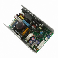
Manufacturer Part Number
GPFM115-5G
Description
PWR SUPPLY MEDICAL PFC 115W 5V
Manufacturer
SL Power Electronics Manufacture of Condor/Ault Brands
Series
GPFM115r
Datasheet
1.GPFM115-48.pdf
(2 pages)
Specifications of GPFM115-5G
Voltage - Output
5.1V
Number Of Outputs
1
Power (watts)
115W
Applications
Medical
Power Supply Type
Switching (Open Frame)
Voltage - Input
85 ~ 264VAC
Mounting Type
Chassis Mount
1st Output
5.1 VDC @ 12A
Size / Dimension
5.25" L x 3.3" W x 1.5" H (113.4mm x 83.8mm x 38.1mm)
Power (watts) - Rated
115W
Operating Temperature
0°C ~ 50°C
Efficiency
81%
Approvals
CE, CSA, IEC, EN, TUV, UL
Line Regulation
2%
Load Regulation
2%
Lead Free Status / RoHS Status
Lead free / RoHS Compliant
3rd Output
-
2nd Output
-
4th Output
-
Other names
271-2656


Notes:
* Add “G” suffix to part number for RoHS compliant model.
A. Maximum continuous current rating for unrestricted convection cooling.
B. Maximum continuous current rating with 150 LFM air or cover option.
C. Add “-C” after voltage in model number for cover with fan option.
SL Power Electronics, Inc. 6050 King Drive, Bldg. A, Ventura, CA, 93003, USA. Phone:(805) 486 4565 Fax:(805) 487 8911 Email: info@slpower.com www.slpower.com Rev.
5/6/08. Data Sheet © 2008 SL Power Electronics, Inc. The information and specifications contained in this data sheet are believed to be correct at time of publication.
However, SL Power accepts no responsibility for consequences arising from reproduction errors or inaccuracies. Specifications are subject to change without notice.
GPFM115 MECHANICAL SPECIFICATIONS
Medical
Model
GPFM115-5
GPFM115-12
GPFM115-13
GPFM115-15
GPFM115-24
GPFM115-28
GPFM115-48
ENVIRONMENTAL SPECIFICATIONS
Temperature (A)
Humidity (A)
Shock (B)
Altitude
Vibration (C)
JI INPUT: (AMP P.C.B. HEADER P.N 640445-5)
PIN 1) AC LINE
PIN 2) = N/C
PIN 3) = AC NEUTRAL
PIN 4) = N/C
PIN 5) = AC GROUND
SIGNALS: J2
AMP P.C.B. HEADER P/N 640456-4
MATING CONNECTOR P/N 640621-4
PIN 1) POWER FAIL
PIN 2) -SENSE
PIN 3) +SENSE
PIN 4) COMMON
FAN: J4
AMP P.C.B. HEADER P/N 640456-2
MATING CONNECTOR P/N 640621-2
PIN 1) -
PIN 2) +
OUTPUT
J3- 5A MAXIMUM CONTINUOUS CURRENT PER
CONNECTOR PIN.
AMP P.C.B. HEADER P/N 640445-8
PIN 1-4) +Vout
PINS 5-8) RETURN
OUTPUT-MATING CONNECTOR AMP P/N
HOUSING 640250-8
CONTACT 770476-1
INPUT MATING CONNECTOR AMP P/N
HOUSING 640250-5
CONTACT 770476-1
MAX. SCREW PROTRUSION THROUGH CHASSIS = 0.08”
[2 MM], CHASSIS THICKNESS = 0.080” [2 MM]
OPTIONAL COVER/FAN ASSEMBLY
AVAILABLE P/N 09-115CF
Suffix*
RoHS
G
G
G
G
G
G
G
Voltage
Output
5.1 V
12 V
13 V
15 V
24 V
28 V
48 V
OPERATING
0 to 50°
0 to 95% RH
20 g
-500 to 10,000 ft
1.5 g
pk
Output Ad-
rms’
justment
0.003 g
±5%
±5%
±5%
±5%
±5%
±5%
±5%
2
/Hz
Maximum (A)
NON-OPERATING
-40 to +85°C
0 to 95% RH
40 g
-500 to 40,000 ft
5 g
Output
6.7 A
6.2 A
5.3 A
3.3 A
2.9 A
1.7 A
12 A
rms’
pk
0.026 g
2
/Hz
Maximum (B)
9.6 A
8.8 A
7.7 A
4.8 A
4.1 A
2.4 A
20 A
A. Units should be allowed to warm up/operate under non-condensing
conditions before application of power. Derate output current and total
output power by 2.5% per °C above 50°C. For operation in a confined
space, moving air may be required. Under all conditions, the cooling vs.
load profile should be such that chassis temperatures do not exceed
90°C for extended periods.
B. Shock testing—half-sinusoidal, 10 ± 3 ms duration, ± direction, 3
orthogonal axes, total 6 shocks.
C. Random vibration—10 to 2000Hz, 6dB/octave roll-off from 350 to
2000Hz, 3 orthogonal axes. Tested for 10 min./axis operating and 1
hr./axis non-operating.
Output Peak
10.8 A
9.9 A
8.7 A
5.4 A
4.6 A
25 A
2.7A
Regulation
Total
2%
2%
2%
2%
2%
2%
2%
18.5 ± 1.5 V
6.2 ± 0.6 V
14 ± 1.1 V
15 ± 1.1 V
28 ± 2.5 V
34 ± 2.8 V
55 ± 4.0 V
Setpoint
OVP
Ripple/
Noise
1%
1%
1%
1%
1%
1%
1%
Notes
C
C
C
C
C
C
C
Related parts for GPFM115-5G
Image
Part Number
Description
Manufacturer
Datasheet
Request
R

Part Number:
Description:
PWR SUPPLY MEDICAL PFC 115W 24V
Manufacturer:
SL Power Electronics Manufacture of Condor/Ault Brands
Datasheet:

Part Number:
Description:
PWR SUPPLY MEDICAL PFC 115W 48V
Manufacturer:
SL Power Electronics Manufacture of Condor/Ault Brands
Datasheet:

Part Number:
Description:
PWR SUPPLY MEDICAL PFC 115W 12V
Manufacturer:
SL Power Electronics Manufacture of Condor/Ault Brands
Datasheet:

Part Number:
Description:
PWR SUPPLY MEDICAL PFC 115W 15V
Manufacturer:
SL Power Electronics Manufacture of Condor/Ault Brands
Datasheet:

Part Number:
Description:
PWR SUPPLY MEDICAL PFC 115W 28V
Manufacturer:
SL Power Electronics Manufacture of Condor/Ault Brands
Datasheet:

Part Number:
Description:
PWR SPLY MEDICAL PFC 115W 48V
Manufacturer:
SL Power Electronics Manufacture of Condor/Ault Brands
Datasheet:

Part Number:
Description:
PWR SPLY MEDICAL PFC 115W 5V
Manufacturer:
SL Power Electronics Manufacture of Condor/Ault Brands
Datasheet:

Part Number:
Description:
PWR SPLY MEDICAL PFC 115W 15V
Manufacturer:
SL Power Electronics Manufacture of Condor/Ault Brands
Datasheet:

Part Number:
Description:
PWR SPLY MEDICAL PFC 115W 12V
Manufacturer:
SL Power Electronics Manufacture of Condor/Ault Brands
Datasheet:

Part Number:
Description:
PWR SPLY MEDICAL PFC 115W 24V
Manufacturer:
SL Power Electronics Manufacture of Condor/Ault Brands
Datasheet:

Part Number:
Description:
PWR SPLY MEDICAL PFC 115W 28V
Manufacturer:
SL Power Electronics Manufacture of Condor/Ault Brands
Datasheet:
Part Number:
Description:
COVER/FAN ASSEMBLY
Manufacturer:
SL Power Electronics Manufacture of Condor/Ault Brands
Datasheet:
Part Number:
Description:
POWER FAIL MODULE
Manufacturer:
SL Power Electronics Manufacture of Condor/Ault Brands

Part Number:
Description:
POE SPLITTER 10W 5V @ 2.00A
Manufacturer:
SL Power Electronics Manufacture of Condor/Ault Brands
Datasheet:

Part Number:
Description:
POE SPLITTER 10.8W 12V @0.9A
Manufacturer:
SL Power Electronics Manufacture of Condor/Ault Brands
Datasheet: