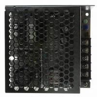
LS50-36 TDK Corporation, LS50-36 Datasheet

LS50-36
Specifications of LS50-36
LS5036
Available stocks
Related parts for LS50-36
LS50-36 Summary of contents
Page 1
LS25~150 Series Instruction Manual BEFORE USING THE POWER SUPPLY UNIT Pay attention to all warnings and cautions before using the unit. Incorrect usage could lead to an electrical shock, damage to the unit or a fire hazard. WARNING and CAUTION ...
Page 2
... Terminal connecting method Input must be off when making connection. Connect FG terminal to ground terminal of the equipment. The output load line and input line shall be separated and twisted to improve noise immunity. LS25, LS35, LS50, LS75 - LOAD + Maximum output current of each output terminal is 25A except for LS25 (15A). ...
Page 3
Explanation of Functions and Precautions 3-1. Input Voltage Range Input voltage range is single phase 88 ~ 264VAC (47 ~ 63Hz) or 125 ~ 373VDC for LS25 ~ LS100. For LS150, selectable switch 115/230VAC will decide the input voltage ...
Page 4
Series Operation For series operation, either method ( possible. Method ( A ) Power Supply Output Terminal Output Terminal Note : In case of Method ( A ), please connect diodes to ...
Page 5
Isolation / Withstand Voltage 4-1. Isolation Test Isolation resistance between output and FG (chassis) shall be more than 100MΩ at 500VDC. For safety, voltage setting of DC isolation tester must be done before the test. Ensure that the unit ...
Page 6
Mounting Directions 5-1. Output Derating according to the Mounting Directions Recommended standard mounting is Method ( A ). Method ( and ( D ) are also possible. Refer to the Output Derating below. Please ...
Page 7
LS25-5, -12, -15, -24, -36 & -48 Output Derating Vs Ambient Temperature Load (%) 120 100 -25 0 LS35-3.3, -5, -12, -15, -24, -36 & -48 Output Derating Vs Ambient Temperature Load (%) 120 ...
Page 8
... LS50-3.3, -5, -12, -15, -24, -36 & -48 Load (%) Output Derating Vs Ambient Temperature 120 100 -25 0 LS75-3.3, -5 Load (%) Output Derating Vs Ambient Temperature 120 100 - Ambient Temperature (° Ambient Temperature (°C) 7 TDK-Lambda LS Series 25-150 INSTRUCTION MANUAL Mounting A, B & D Mounting C 100 75 Mounting A, B & D Mounting C 100 ...
Page 9
LS75-12, -15, -24, -36 & -48 Load (%) Output Derating Vs Ambient Temperature 120 100 -25 0 LS100-3.3, -5 Output Derating Vs Ambient Temperature Load (%) 120 100 ...
Page 10
LS100-12, -15, -24, -36 & -48 Output Derating Vs Ambient Temperature Load (%) 120 100 -25 0 LS150-3.3, -5 Load (%) Output Derating Vs Ambient Temperature 120 100 ...
Page 11
... Output Derating versus Input Voltage (Convection Cooling) LS100-3.3, -5, -12, -15, -24, -36 & -48 Output Derating Vs Input Voltage LOAD (%) 120 100 115 88 NOTE : LS25, LS35, LS50, LS75 & LS150 series do not require Input Voltage Derating Ambient Temperature (°C) 230 Vin (VAC) 10 TDK-Lambda LS Series 25-150 ...
Page 12
Mounting Method 1) This is convection cooling type power supply. In consideration of the heat radiation and safety, please keep a dis- tance of more than 15mm between the power supply and the peripheral parts. When lining up multiple ...
Page 13
... Refer to the following fuse rating when selecting the external input fuse. Surge current flows when input turns on. Fuse rating is specified by Inrush Current value at input turn on. Do not select the fuse according to input current (rms) values under the actual load condition. LS25 : F1.6A , 250V LS35, LS50 : T2A , 250V LS75 : T2.5A , 250V ...


