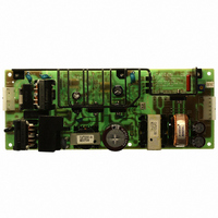
ZWS150PAF48 TDK Corporation, ZWS150PAF48 Datasheet - Page 9

ZWS150PAF48
Manufacturer Part Number
ZWS150PAF48
Description
PWR SUP 48V 148.8W 3.1A
Manufacturer
TDK Corporation
Series
ZWSr
Specifications of ZWS150PAF48
Voltage - Output
48V
Number Of Outputs
1
Power (watts)
150W
Applications
Commercial
Power Supply Type
Switching (Open Frame)
Voltage - Input
85 ~ 265VAC
Mounting Type
Chassis Mount
1st Output
48 VDC @ 3.1A
Size / Dimension
8.19" L x 3.15" W x 1.46" H (208mm x 80mm x 37mm)
Power (watts) - Rated
148.8W
Operating Temperature
-10°C ~ 70°C
Efficiency
82%
Approvals
CE, CSA, EN, UL
Line Regulation
0.4%
Load Regulation
0.8%
Lead Free Status / RoHS Status
Lead free / RoHS Compliant
3rd Output
-
2nd Output
-
4th Output
-
Other names
285-1713
(B) To use as Back-up Power Supply
3-10. Peak Output Current
For ZWS150PAF series, the peak output current should
satisfy the conditions below:
1)Should not exceed the rated peak current in the
2)Duty cycle of the peak output current should be < 35%,
3)The relation between peak output current with maximum
Terminal
Terminal
specifications.(eg. 12A for ZWS150PAF-24)
and operating time of peak output current is less than 10
seconds. If the power supply is operated under convec-
tion cooling, and ambient exceeds 50
operating period for peak current is recommended.
average output current is defined as below:
Ambient Temperature ( C)
Output
Output
1. Set power supply output voltage higher by the for-
2. Adjust the output voltage of each power supply to
3. Use within the specifications for output voltage and
Output
Terminal
Output
Terminal
Supply
Power
ward voltage drop(V
be the same.
output power.
+50 C onwards
Supply
-10 ~ +50 C
Power
o
o
o
F
) of diode
Peak current operating time
within 10 seconds
within 5 seconds
o
C, the following
Load
Load
- 8 -
Ip = Peak output current
Im = Minimum output current
D = Duty cycle,
τ
T = Period
Io = Maximum allowable average output current of speci-
Formula:
Example I : For ZWS150PAF-24 at Ta =60 C,Mounting A,
Example II : Following table illustrate some peak load op-
Please note that the actual Io in peak load operation is low .
3-11. Remote ON/OFF Control
Remote ON/OFF control (CN2,CN52) function is avail-
able. Using this function allows the user to turn the output
on and off without having to turn the AC input on and off.
Remote ON/OFF control can be used by following 2 modes.
However, for Cover and Chassis type (eg. ZWS150PAF/A,
/JA, /TA, /SA) cannot be used.
Ip
Im
Average Load(%)
0A
= Peak output current operating time
derating by various
Mounting and Ta :
average load after
fications (Io should be average load after derating at
various mounting and ambient temperature)
Max allowable
100%
90%
80%
70%
60%
50%
40%
30%
20%
10%
ZWS150PAF:
(A): In case of Im =0, Ip =12A,
(B): In case of Im =2A, Ip =12A,
τ
Max Io =4.41A (after 70% Derating)
1.4 Io
D<18.9%
D<16.6%
eration examples for ZWS150PAF-24.
T
τ
/T
2
Io(A)
5.67
5.04
4.41
3.78
3.15
2.52
1.89
1.26
0.63
> Ip
6.3
1.4 Io
2
Ip (A)max D max
DENSEI-LAMBDA
ZWS150PAF Series
INSTRUCTION MANUAL
D + Im
Examples of peak load
derating, calculated by
12
12
12
12
12
12
12
12
12
12
2
above formula
> Ip
2
2
(1-D)
35.0%
31.3%
24.7%
18.9%
13.9%
9.7%
6.2%
3.5%
1.5%
0.4%
D + Im
o
Im (A)
2
2.83
0
0
0
0
0
0
0
0
0
(1-D)
Actual
Io(A)
6.04
3.75
2.96
2.27
1.67
1.16
0.74
0.42
0.18
0.05
Io


