S82J-10015D Omron, S82J-10015D Datasheet - Page 13
S82J-10015D
Manufacturer Part Number
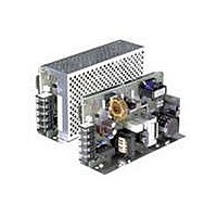
S82J-10015D
Description
POWER SUPPLY SWITCHING 15V 7A
Manufacturer
Omron
Series
S82Jr
Specifications of S82J-10015D
Voltage - Output
15V
Number Of Outputs
1
Power (watts)
100W
Applications
Commercial
Power Supply Type
Switching (Closed Frame)
Voltage - Input
120, 240VAC
Mounting Type
Chassis Mount
1st Output
15 VDC @ 7A
Size / Dimension
3.82" L x 7.4" W x 1.97" H (97mm x 188mm x 50mm)
Power (watts) - Rated
100W
Operating Temperature
-10°C ~ 60°C
Efficiency
75%
Approvals
CE, CSA, UL, VDE
Lead Free Status / RoHS Status
Lead free / RoHS Compliant
3rd Output
-
2nd Output
-
4th Output
-
Lead Free Status / Rohs Status
Lead free / RoHS Compliant
Other names
S82J10015D


If operation amplifiers as loads are connected in series, connect a diode between the positive and negative output terminals of each
Switching Power Supplies as shown in the illustration below. Without these diodes, the Power Supplies may not start when power is
turned on, possibly damaging internal circuits over a period of time.
Use Schottky barrier diodes with a low forward voltage (V
Guidelines for the dielectric strength and current of the diodes are as follows:
Dielectric strength: At least twice the rated output voltage of the Power Supply
Forward current:
No diodes are required for models that allow series operation.
J SERIES OPERATION
Only models with power ratings of 50/100/150/300/600 W allow series operation.
As shown in the following diagram, the output voltage from each Switching Power Supply can be added.
With the S82J-050jjjj or S82J-10024jj, if the load is shorted a reverse voltage may result in the Power Supply causing deteriora-
tion and damage. It is recommended that diodes are connected as shown in the previous diagram (D
J PARALLEL OPERATION
Only 300- and 600-W models can be in parallel operation. Do not operate any other models in parallel. The output of the models in paral-
lel operation is a maximum of 80% of the rated output.
Set the parallel operation selector to PARALLEL if the Units are in parallel operation and make sure that the thickness and the length of all
wires connected to the load are the same to ensure that the wires will have no voltage drop differences.
J GENERATING OUTPUT VOLTAGE (
An output of
13
±
INPUT
INPUT
Switching Power Supply
can be generated by using two power supplies as shown below, because the power supply produces a floating output.
INPUT
INPUT
INPUT
INPUT
At least twice the rated output current
+V
–V
+V
–V
INPUT
INPUT
+ V
– V
+ V
– V
+ V
– V
+ V
– V
+V
–V
+V
–V
D
D
2
1
D
Load
Load
D
1
2
S82J
Load
Load
±
F
). Other types of diodes will not be effective.
)
Load
Load
1
, D
2
).
Related parts for S82J-10015D
Image
Part Number
Description
Manufacturer
Datasheet
Request
R

Part Number:
Description:
POWER SUPPLY 5V 2A OPEN FRAME
Manufacturer:
Omron
Datasheet:

Part Number:
Description:
POWER SUPPLY 24V .5A OPEN FRAME
Manufacturer:
Omron
Datasheet:

Part Number:
Description:
POWER SUPPLY 24V 1.1A OPEN FRAME
Manufacturer:
Omron
Datasheet:

Part Number:
Description:
Use S8VM-05005
Manufacturer:
Omron
Datasheet:

Part Number:
Description:
POWER SUPPLY 24V 2.1A OPEN FRAME
Manufacturer:
Omron
Datasheet:

Part Number:
Description:
POWER SUPPLY SWITCHING 5V 2A
Manufacturer:
Omron
Datasheet:

Part Number:
Description:
POWER SUPPLY SWITCHING 12V 1A
Manufacturer:
Omron
Datasheet:

Part Number:
Description:
POWER SUPPLY SWITCHING 12V 1A
Manufacturer:
Omron
Datasheet:
Part Number:
Description:
POWER SUPPLY SWITCHING 15V .7A
Manufacturer:
Omron
Datasheet:

Part Number:
Description:
G6S-2GLow Signal Relay
Manufacturer:
Omron Corporation
Datasheet:
Part Number:
Description:
Compact, Low-cost, SSR Switching 5 to 20 A
Manufacturer:
Omron Corporation
Datasheet:
Part Number:
Description:
Manufacturer:
Omron Corporation
Datasheet: