NFS110CJ Emerson Network Power, NFS110CJ Datasheet - Page 4
NFS110CJ
Manufacturer Part Number
NFS110CJ
Description
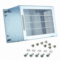
POWER SUPPLY MOUNTING KIT COVER
Manufacturer
Emerson Network Power
Series
NFS110r
Specifications of NFS110CJ
Accessory Type
Enclosure Kit
For Use With/related Products
NFS110 Artesyn Power Supplies
Lead Free Status / RoHS Status
Lead free / RoHS Compliant
Other names
454-1310


Mechanical Notes
A Metallic or non-metallic stand-offs (maximum diameter 5.4mm) can be used in
B The ground pad of the mounting hole near J1, allows system grounding
C The heat sink is grounded, and allows system grounding by mechanical
D The supply must be mechanically supported using the PCB mounting holes and
E
F
all four mounting holes without effecting safety approval.
through a metal stand-off to the system chassis.
connection to the system chassis.
may be additionally supported by the heatsink mounting holes.
It is always advisable to attach the power supply heat sink to another thermal
dissipator (such as a chassis or finned heatsink etc). The resulting decrease in
heat sink mounted component temperatures will improve power supply
lifetime.
A standard L-bracket and cover is available for mounting which contains all
screws, connectors and necessary mounting hardware. The kit is available,
order part number “NFS110CJ” .
AC (J1) mating connector
Molex 09-50-3051 or Molex 09-91-0500 mating connector with 2478
or equivalent crimp terminals.
DC (J2) mating connector
Molex 09-50-3131 or Molex 09-91-1300 mating connector with 2478
or equivalent crimp terminals.
0.050 0.020
(1.27)
0.250
0.010
(6.35)
1.80 (45.72) MAX
(107.95)
4.250
0.020
(95.25)
3.750
0.005
(6.35)
0.250
0.010
C6
3.35 0.015 (85.09)
T1
T1
ALL DIMENSIONS IN INCHES (mm)
6.50 0.005 (165.1)
7.00 0.020 (177.8)
Pin 1
Optional
Power Fail
Detect Circuit
(Key = Pin 2)
Voltage Adjust
1.55 0.005
(39.37)
L1
5A, 250 VAC
F1
J1
J2
5V OUTPUT
PFD SIGNAL
AC INPUT
6-32 UNC
(4PL)
OPTIONAL POWER FAIL DETECT TIMING DIAGRAM
(12.07)
0-0.4 MAX
0.475
0.010
4.75V
LOW
PIN 1
0.156
DIA. HOLE
(4PL)
PIN 1
1.00 0.005
(25.4)
T1
HIGH
J1
Pin 1
Pin 2
Pin 3
J2
Pin 1
Pin 2
Pin 3
Pin 4
Pin 5
Pin 6
Pin 7
Pin 8
Pin 9
Pin 10
Pin 11
Pin 12
Pin 13
T2
3.5V MIN
4.75V
T3
AC Ground
AC Neutral
-7901PJ
AC Line
Return
Return
Return
Return
+5.1 V
+5.1 V
+5.1 V
+12 V
+12 V
-12 V
-5 V
PFD
110W
80W
11W
0W
0C
Power fail detect signal (Note 8)
50ms ≤ T1 ≤ 200ms
T2 will vary with line and load
T3 ≥ 3ms
Pout: 110W
PFD output is an open collector which
will sink ≤ 40mA in the low state.
DERATING CURVE
Output Power (Watts)
Embedded Power for
Business-Critical Continuity
Pin Connections
10C
20 CFM FORCED AIR COOLING
AC Ground
AC Neutral
11W MINIMUM LOAD REQUIRED AT 230VAC
Removed for Key
-7902PJ
AC Line
Return
Return
Return
Return
+5.1 V
+5.1 V
+5.1 V
+12 V
+12 V
+24 V
-12 V
PFD
20C
CONVECTION
NATURAL
COOLING
(See Notes 9, 10)
30C
AC Ground
AC Neutral
-7904PJ
AC Line
40C
Return
Return
Return
Return
+5.1 V
+5.1 V
+5.1 V
+15 V
+15 V
-15 V
-5 V
PFD
N/C = no connection.
50C
60C
NFS110 Series
AC Ground
AC Neutral
Rev. 06.10.08
SINGLES
AC Line
Return
Return
Return
Return
V
V
V
V
V
N/C
N/C
N/C
out
out
out
out
out
70C
55W
40W
4 of 5
Related parts for NFS110CJ
Image
Part Number
Description
Manufacturer
Datasheet
Request
R

Part Number:
Description:
POWER SUPPLY QUAD OUTPUT
Manufacturer:
Emerson Network Power
Datasheet:

Part Number:
Description:
PS MEDICAL 5.1/24/12/-12V 110W
Manufacturer:
Emerson Network Power
Datasheet:

Part Number:
Description:
POWER SUPPLY SWITCHER 12V 110W
Manufacturer:
Emerson Network Power
Datasheet:
Part Number:
Description:
POWER SUPPLY SWITCHER 24V 110W
Manufacturer:
Emerson Network Power
Datasheet:
Part Number:
Description:
POWER SUPPLY QUAD OUTPUT
Manufacturer:
Emerson Network Power
Datasheet:
Part Number:
Description:
POWER SUPPLY 15V 5 AMP
Manufacturer:
Emerson Network Power
Datasheet:
Part Number:
Description:
POWER SUPPLY SWITCHER 5.1V 110W
Manufacturer:
Emerson Network Power
Datasheet:
Part Number:
Description:
POWER SUPPLY, SWITCH MODE, 24V
Manufacturer:
Emerson Network Power
Datasheet:
Part Number:
Description:
PS SWITCHER MEDICAL 24V 110W
Manufacturer:
Emerson Network Power
Datasheet:
Part Number:
Description:
PS SWITCHER 5.1/12/-12/-5V 110W
Manufacturer:
Emerson Network Power
Datasheet:
Part Number:
Description:
AC/DC Front end 12Vo 36A 12Vsb Standard Airflow
Manufacturer:
Emerson Network Power

Part Number:
Description:
POWER SUPPLY DIN 24VDC 10A
Manufacturer:
Emerson Network Power
Datasheet:

Part Number:
Description:
POWER SUPPLY SGL 48VOUT 40W 3X5"
Manufacturer:
Emerson Network Power
Datasheet:

Part Number:
Description:
POWER SUP MED&ITE 48V 45W 2"X4"
Manufacturer:
Emerson Network Power
Datasheet:

Part Number:
Description:
POWER SUPPLY 60W 12V OUT
Manufacturer:
Emerson Network Power
Datasheet: