MA240014 Microchip Technology, MA240014 Datasheet - Page 5
MA240014
Manufacturer Part Number
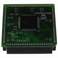
MA240014
Description
MODULE PLUG-IN PIC24
Manufacturer
Microchip Technology
Series
PIC®r
Datasheet
1.MA240014.pdf
(24 pages)
Specifications of MA240014
Accessory Type
Plug-In Module (PIM) - PIC24FJ256GB110
Product
Microcontroller Modules
Data Bus Width
16 bit
Core Processor
PIC24FJ256GB110
Operating Supply Voltage
3 V to 3.6 V
Development Tools By Supplier
Integrated Development Environment, Assembler, ANSI C Compiler
Processor Series
PIC24F
Silicon Manufacturer
Microchip
Core Architecture
PIC
Core Sub-architecture
PIC24
Silicon Core Number
PIC24F
Silicon Family Name
PIC24FJxxGBxxx
Lead Free Status / RoHS Status
Lead free / RoHS Compliant
For Use With/related Products
Explorer 16 (DM240001 or DM240002)
For Use With
DM240001 - BOARD DEMO PIC24/DSPIC33/PIC32
Lead Free Status / Rohs Status
Lead free / RoHS Compliant
Available stocks
Company
Part Number
Manufacturer
Quantity
Price
Company:

Part Number:
MA240014
Manufacturer:
Microchip Technology
Quantity:
135


(11.53 x 10.34 x 2.31 mm)
dsPIC DSC Packages
Hardware DMA (dsPIC33F)
Power Management
Operating Range dsPIC30F
Operating Range dsPIC33F
(17.88 x 10.34 x 2.31 mm)
High Performance DSC CPU
dsPIC30F/dsPIC33F Features Overview
SO: 18-pin SOIC
8 channel DMA
2 KB dual port RAM
Switch between clock sources in real-time
Programmable power-on reset start up
Programmable low-voltage detect
Programmable brown-out reset
Idle and Sleep modes with fast wake-up
DC to 30 MIPS*
V
Ind. (-40° to 85° C) and ext. (-40° to 125°C)
*30 MIPS @ 4.5 to 5.5V, -40° to 85° C
DC to 40 MIPS
V
Ind.(-40° to 85° C) Extended temp. planned
Single core combines MCU and DSP features
C compiler optimized instruction set
16-bit wide data path
24-bit wide instructions
84 base instructions: mostly 1 word/1 cycle
16 16-bit general purpose registers
2 40-bit accumulators
•With rounding and saturation options
Flexible and powerful addressing modes
•Indirect, modulo and bit-reversed
Software stack
16 x 16 fractional/integer multiplier
32/16 and 16/16 divide
Single cycle multiply-and-accumulate
40-stage barrel shifter
DD
DD
SO: 28-pin SOIC
range: 2.5 to 5.5V
range: 3.0 to 3.6V
(22.81 x 7.95 x 3.3 mm)
P: 18-pin PDIP
(10 mm x 10 mm x 1 mm)
(34.67 x 7.87 x 3.3 mm)
PT: 44-pin TQFP
SP: 28-pin SPDIP
(6 mm x 6 mm x 0.9 mm)
MM: 28-pin QFN
Timers/Capture/Compare/PWM
Interrupt Controller
On-chip Flash, Data EE and RAM
System Management
Digital I/O
Flexible clock options:
•Primary external clock, crystal, resonator
•Secondary lower power 32 kHz oscillator
•Internal RC: fast or low power
•Integrated low jitter PLL
Programmable power-up timer
Oscillator start-up timer/stabilizer
Watchdog Timer with its own RC oscillator
Clock switching/fail-safe clock monitor
5 cycle fi xed latency
Up to 118 interrupt sources, up to 5 external
7 programmable priority levels
4 processor exceptions and software traps
Up to 85 programmable digital I/O pins
Wake-up/Interrupt-on-change on up to 24 pins
25 mA sink and source on all dsPIC30F I/O pins
Flash program memory: up to 256 KB
dsPIC30F Data EEPROM: up to 4 KB
•1 million erase/write cycles typical
Data RAM: up to 30 KB
Timer/counters: up to nine 16-bit timers
•Can pair up to make 32-bit timers
•1 timer can run as real-time clock
Input capture: up to 8 channels
•Capture on rising, falling or both edges
•4-deep FIFO on each capture
Output compare: up to 8 channels
•Single or dual 16-bit compare mode
•16-bit glitchless PWM mode
-- PLL sourced by ext. & int. clock sources
(12 mm x 12 mm x 1 mm)
PT: 80-pin TQFP
(52.27 x 15.24 x 3.81 mm)
(8 mm x 8 mm x 0.9 mm)
P: 40-pin PDIP
ML: 44-pin QFN
(14 mm x 14 mm x 1 mm)
PF: 80-pin TQFP
Motor Control Peripherals
Analog-to-Digital Converters
Communication Modules
Motor Control PWM: up to 8 outputs
•4 duty cycle generators
•Independent or complementary mode
•Programmable dead time settings
•Edge or center-aligned
•Manual output override control
•Up to 2 fault inputs
•A/D samples triggered by PWM module
Quadrature encoder interface module
•Phase A, Phase B and index pulse input
10-bit A/D converter:
•dsPIC30F: 1Msps, 1 module
•dsPIC33F: 1.1 Msps, 1 or 2 modules
•Up to 8 simultaneous sample/hold
12-bit A/D converter:
•dsPIC30F: 200 ksps, 1 module
•dsPIC33F: 500 ksps, 1 or 2 modules
Common features:
•±1 LSb accuracy
•16-deep result buffer
•dsPIC30F: up to 16 channels, auto scanning
•dsPIC33F: up to 32 channels, auto scanning
(6 mm x 6 mm x 0.9 mm)
3-wire SPI™: up to 2 modules
•Framing supports I/O interface to simple codecs
I²C™: up to 2 modules
•Full Multi-master and Slave mode support
•7-bit and 10-bit addressing
UART: up to 2 modules
•Interrupt-on-address bit detect
•Wake-up on Start bit from Sleep mode
•4-character TX and RX FIFO buffers
Codec interface module
•Supports I²S and AC97 protocols
CAN/ECAN 2.0B active: up to 2 modules
•3 transmit, 2 receive buffers (dsPIC30F)
•8 transmit, 32 receive buffers (dsPIC33F)
•Wake-up on CAN message
ML: 28-pin QFN
(14 mm x 14 mm x 1 mm)
(12 mm x 12 mm x 1 mm)
PF: 64-pin TQFP
PT: 100-pin TQFP
(10 mm x 10 mm x 1 mm)
(14 mm x 14 mm x 1 mm)
PT: 64-pin TQFP
PF: 100-pin TQFP
5
Related parts for MA240014
Image
Part Number
Description
Manufacturer
Datasheet
Request
R

Part Number:
Description:
Manufacturer:
Microchip Technology Inc.
Datasheet:
Part Number:
Description:
Manufacturer:
Microchip Technology Inc.
Datasheet:
Part Number:
Description:
Manufacturer:
Microchip Technology Inc.
Datasheet:
Part Number:
Description:
Manufacturer:
Microchip Technology Inc.
Datasheet:
Part Number:
Description:
Manufacturer:
Microchip Technology Inc.
Datasheet:
Part Number:
Description:
Manufacturer:
Microchip Technology Inc.
Datasheet:
Part Number:
Description:
Manufacturer:
Microchip Technology Inc.
Datasheet:
Part Number:
Description:
Manufacturer:
Microchip Technology Inc.
Datasheet: