MA180021 Microchip Technology, MA180021 Datasheet - Page 18
MA180021
Manufacturer Part Number
MA180021
Description
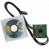
MODULE PLUG-IN 18F87J50 FS USB
Manufacturer
Microchip Technology
Series
PIC®r
Specifications of MA180021
Accessory Type
Plug-In Module (PIM) - PIC18F87J50
Silicon Manufacturer
Microchip
Core Architecture
PIC
Core Sub-architecture
PIC18
Features
Full Speed USB Demonstration, Operated Either Stand Alone Or As Plug-In Module
Silicon Core Number
PIC18F
Silicon Family Name
PIC18FxxJxx
Lead Free Status / RoHS Status
Lead free / RoHS Compliant
For Use With/related Products
HPC Explorer Board (DM183022) or PIC18 Explorer Board (DM183032)
For Use With
DM183032 - BOARD EXPLORER PICDEM PIC18DM183022 - BOARD DEMO PIC18FXX22 64/80TQFP
Lead Free Status / RoHS Status
Lead free / RoHS Compliant
Available stocks
Company
Part Number
Manufacturer
Quantity
Price
Company:

Part Number:
MA180021
Manufacturer:
Microchip Technology
Quantity:
135


3.5
3.6
3.7
DS51678A-page 14
LEDs
PUSH BUTTONS
JUMPERS
In addition to providing a convenient location for installing a digital current meter, JP4
also serves another purpose. In some cases, it may be undesirable to consume power
from the USB port, for example, when developing end applications that are always
self-powered or consume more than 300 mA (the maximum rating for the regulator). In
these cases, jumper cap, JP4, can be removed, and the PIM can obtain power from the
HPC Explorer board or directly from the test points.
Diode, D2, prevents the PIM from ever sourcing current onto the +5V V
USB cable. The USB 2.0 specifications require that USB peripherals should never
source current onto the +5V V
Two high-efficiency, red LEDs have been included on the PIM. The LEDs are
connected to I/O pins, RE0 and RE1, and may be used for general purpose indication.
The LEDs are connected such that they turn on when the I/O pin controlling them is
driven high. Alternatively, if the I/O pin loading is undesirable (each LED consumes
approximately 1 mA when turned on), jumper cap covering, JP5, may be removed. This
will effectively disconnect both LEDs from their respective I/O pins.
Two miniature push buttons are included on the PIM. Switch, S3 on the PIM, connects
to MCLR. It may be used to reset the microcontroller when the PIM is used either
stand-alone or while connected to the HPC Explorer board.
Pin, RB4 on the PIC18F87J50 microcontroller, is pulled up to V
resistor (R26 on the PIM). If push button, S4 on the PIM, is pressed, it will pull RB4 low.
This push button may be used for any general purpose user interfacing purposes.
When the PIM is plugged into the HPC Explorer board, the RB0 push button on the
HPC Explorer will also work and can be used for additional general purpose user input.
The PIM has three jumper headers on it to provide additional flexibility for
experimentation and development purposes.
JP1 – This is a three-pin header with the labels, ‘I’, ‘R’ and ‘U’. The ‘R’ is an abbreviation
referring to microcontroller pin, RB5. ‘I’ is an abbreviation referring to the “ICE” female
header pin for the RB5 signal. ‘U’ is an abbreviation for the USB V
When the jumper is in the ‘R’ to ‘I’ position, the RB5 pin connects only to the ICE female
header pin, just like most of the other general purpose I/O pins. When the jumper is in
the ‘R’ to ‘U’ position, RB5 (which is 5.5V tolerant) can be used to sense when the USB
cable has been attached to the host, and when the host is actively providing power to
the +5V V
the D+ or D- lines high (such as with the D+ or D- pull-up resistor) until the host actively
powers the +5V V
ever sourcing even small amounts of power to the host when the host is not powered.
Small amounts of current could potentially prevent the host (and possibly other USB
peripherals connected to that host) from fully becoming depowered, which may cause
problems during power-up and initialization.
BUS
line. According to the USB 2.0 specifications, no device should ever pull
BUS
line. This is intended to prevent self-powered peripherals from
BUS
line under any condition.
© 2007 Microchip Technology Inc.
DD
through a 15 kOhm
BUS
line.
BUS
pin of the
Related parts for MA180021
Image
Part Number
Description
Manufacturer
Datasheet
Request
R

Part Number:
Description:
Manufacturer:
Microchip Technology Inc.
Datasheet:
Part Number:
Description:
Manufacturer:
Microchip Technology Inc.
Datasheet:
Part Number:
Description:
Manufacturer:
Microchip Technology Inc.
Datasheet:
Part Number:
Description:
Manufacturer:
Microchip Technology Inc.
Datasheet:
Part Number:
Description:
Manufacturer:
Microchip Technology Inc.
Datasheet:
Part Number:
Description:
Manufacturer:
Microchip Technology Inc.
Datasheet:
Part Number:
Description:
Manufacturer:
Microchip Technology Inc.
Datasheet:
Part Number:
Description:
Manufacturer:
Microchip Technology Inc.
Datasheet: