CDB2000-PC-LCO Cirrus Logic Inc, CDB2000-PC-LCO Datasheet - Page 12
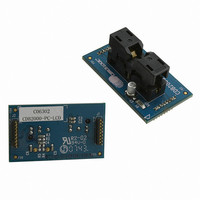
CDB2000-PC-LCO
Manufacturer Part Number
CDB2000-PC-LCO
Description
BOARD EVAL GEN PURPOSE PLL DC
Manufacturer
Cirrus Logic Inc
Datasheet
1.CDB2000-PC-LCO.pdf
(26 pages)
Specifications of CDB2000-PC-LCO
Accessory Type
Daughter Card
Product
Audio Modules
Lead Free Status / RoHS Status
Contains lead / RoHS non-compliant
For Use With/related Products
CDB2000-MB
For Use With
598-1491 - BOARD EVAL GEN PURPOSE PLL
Lead Free Status / Rohs Status
Lead free / RoHS Compliant
Other names
598-1493


12
3.6
3.7
4. HARDWARE USAGE AND OPERATION
4.1
4.1.1
4.1.2
If the CDB2000-MB platform is connected to a PC via USB and the CDK2000 Configuration Wizard host
software has established communications with the board, D8 will be lit to indicate micro-controller software
mode. (Note that micro-controller software mode doesn't mean the DUT operates in software mode, which
is entirely independent. It just means that the micro-controller is communicating with the CDK2000 Config-
uration Wizard software on a PC.)
The micro-controller interfaces with other blocks on the board via various logic signals. It receives input from
push-button S1 and DIP switch positions 5 and 6. It also generates various control and status signals.
VDUT.PROG.EN
DUT.PROG.SUCC, and DUT.PROG.FAIL indicate various status and error conditions via LED D5/6/7.
DUT.HW/SW controls the board-level logic to correspond with the operational mode of the DUT.
DUT Software Mode Control
In software mode, the DUT communicates with the micro-controller via I²C
are routed through Q5/Q7 and Q8/Q4, respectively, which are all “on” when DUT.SW/HW is high (via invert-
er U1-C). D10 is lit to indicate that the DUT is in software mode. (Note that DUT software mode is indepen-
dent of micro-controller software or hardware mode. The DUT automatically enters software mode when it
detects a valid I²C transaction on its control port and must be reset to enter hardware mode. The micro-
controller transitions the board-level logic between hardware and software modes as needed to match the
DUT hardware/software mode.)
Hardware Mode Control
When the DUT is in hardware mode, its operational state is determined by the three mode pins (M2:0). In
this case DIP switch positions 2, 3, and 4 directly connect to the mode pins since Q9/10/11 are “on” due to
the micro-controller driving DUT.HW/SW high, and Q4/5/7/8 are “off” due to DUT.SW/HW being low (via in-
verter U1-C). When a DIP switch is in the lower (closed) position, the corresponding mode pin is logic 0;
when a DIP switch is in the upper (open) position, the corresponding mode pin is logic 1 (via pull-up resistors
R52/53/54). D9 is lit to indicate that the DUT is in hardware mode.
General Considerations
Power Supply
A USB connection is required to power the CDK2000 platform and the DUT. If the board is to be used in
software mode, it must be connected to a PC, either directly or via a self-powered hub. If board operation
in software mode is not required, an alternate USB power supply (such as a wall adapter) may be used
instead. The latter is useful for DUTs that only operate in hardware mode or in a production environment
where multiple DUTs are to be programmed on an assembly floor and a PC is not available for each work-
station.
Input and Output Clocks
Connect the desired input clock sources as described in
from the motherboard (-CLK daughter card option), use DIP switch position 1 to toggle the REF_CLK
source between the BNC connector (J6) and the on-board oscillator (Y1). If REF_CLK is generated locally
(-XTL, -OSC, and -LCO daughter card options), set DIP switch position 1 to the open (BNC) position and
disconnect any external clock sources from J6 in order to minimize clock interferences.
Observe the desired clock outputs on J7 and J4 as described in
and
VDUT.EN
control
the
power
Section 3.3 on page
supply
Section 3.4 on page
to
the
®
. The I²C clock and data lines
11. If REF_CLK is sourced
DUT.
11.
DUT.PROG.RUN,
CDK2000
DS821DB1
Related parts for CDB2000-PC-LCO
Image
Part Number
Description
Manufacturer
Datasheet
Request
R

Part Number:
Description:
BOARD EVAL GEN PURPOSE PLL
Manufacturer:
Cirrus Logic Inc
Datasheet:

Part Number:
Description:
BOARD EVAL GEN PURPOSE PLL DC
Manufacturer:
Cirrus Logic Inc
Datasheet:

Part Number:
Description:
BOARD EVAL GEN PURPOSE PLL
Manufacturer:
Cirrus Logic Inc
Datasheet:
Part Number:
Description:
Development Kit
Manufacturer:
Cirrus Logic Inc
Datasheet:
Part Number:
Description:
Development Kit
Manufacturer:
Cirrus Logic Inc
Datasheet:


Part Number:
Description:
High-efficiency PFC + Fluorescent Lamp Driver Reference Design
Manufacturer:
Cirrus Logic Inc
Datasheet:
Part Number:
Description:
Development Kit
Manufacturer:
Cirrus Logic Inc
Datasheet:
Part Number:
Description:
Development Kit
Manufacturer:
Cirrus Logic Inc
Datasheet:

Part Number:
Description:
Development Kit
Manufacturer:
Cirrus Logic Inc
Datasheet:
Part Number:
Description:
Development Kit
Manufacturer:
Cirrus Logic Inc
Datasheet:
Part Number:
Description:
Development Kit
Manufacturer:
Cirrus Logic Inc
Datasheet:
Part Number:
Description:
Development Kit
Manufacturer:
Cirrus Logic Inc
Datasheet:

Part Number:
Description:
Ref Bd For Speakerbar MSA & DSP Products
Manufacturer:
Cirrus Logic Inc