AOB-IBRS232 Amulet Technologies LLC, AOB-IBRS232 Datasheet - Page 2
AOB-IBRS232
Manufacturer Part Number
AOB-IBRS232
Description
BOARD INTERFACE ONBOARD RS232
Manufacturer
Amulet Technologies LLC
Datasheet
1.AOB-IBRS232.pdf
(2 pages)
Specifications of AOB-IBRS232
Accessory Type
Serial Interface Board: RS-232
Module Size (w X H X T)
160 mm x 109 mm x 11.4 mm
Background Color
White
Attached Touch Screen
Yes
Product
GUI Processor
Style
Amulet On-Board Module
Interface
RS-232
Lead Free Status / RoHS Status
Lead free / RoHS Compliant
For Use With/related Products
5.7" Amulet OnBoard Modules
Lead Free Status / Rohs Status
Lead free / RoHS Compliant
Other names
681-1009
AOB-1BRS232
AOB-1BRS232
Available stocks
Company
Part Number
Manufacturer
Quantity
Price
Company:

Part Number:
AOB-IBRS232
Manufacturer:
Amulet Technologies
Quantity:
135


The serial parameters for communications between the Amulet client and the
server are, as follows:
Baud Rate: 9600, 19200, 57600, or 115200bps
Parity: None
Data Bits: 8
Stop Bits: 1
See Communications
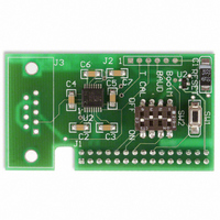
DIP Switch Settings
The Easy GUI controller board can be powered up in different modes via the
settings of the DIP switch (SW2). Some of the power up modes include:
programming mode, run mode, RAM test mode, and touch panel mode.
Boot Mode (Switch 1) -- This switch is monitored during a reboot to determine
the operational mode of the controller board; ON is the normal mode and OFF is
the FLASH program mode. The only time you should have to set Switch 1 to OFF
(program mode) is when the project you compiled locks up the Amulet OS to the
point where it won't accept the wake up message or if the Amulet OS has been
corrupted and you need to
Flash Mode Baud Rate (Switch 2) -- This switch sets the baud rate used during
a Flash Reprogram. The ON position sets the hardware to 19,200 baud; OFF
sets the hardware to 115,200 baud. This setting must match the baud rate
selected in the Amulet Compiler software.
Touch panel Mode (Switch 4) -- This switch should remain ON during normal
operation. Turn this switch OFF and then reboot the controller board to begin a
touch panel calibration. The controller will display a series of three calibration
targets. Use a stylus to touch the center of each target. If necessary, the
controller will repeat the calibration. When calibration is complete, the controller
will return to normal operation. The switch must be returned to the normal mode
(ON) before the next reboot to continue normal operation.
Protocol
Figure 5. DIP Switch Settings
reload the
Switch 1 -- Boot Mode
Switch 2 -- Flash Mode Baud Rate
Switch 3 – N/C
Switch 4 – Touch panel Mode
for more information.
OS.
Rev. A 8/12/05
Related parts for AOB-IBRS232
Image
Part Number
Description
Manufacturer
Datasheet
Request
R

Part Number:
Description:
KIT STARTER 3.8" MODULE
Manufacturer:
Amulet Technologies LLC
Datasheet:

Part Number:
Description:
KIT STARTER 5.7" ONBOARD MODULE
Manufacturer:
Amulet Technologies LLC
Datasheet:

Part Number:
Description:
IC GUI PROC 24BIT COLOR 208PQFP
Manufacturer:
Amulet Technologies LLC
Datasheet:

Part Number:
Description:
SOFTWARE AMULET COMPILER
Manufacturer:
Amulet Technologies LLC
Datasheet:

Part Number:
Description:
LCD Graphic Display Modules & Accessories GEMboard Display Driver Board
Manufacturer:
Amulet Technologies LLC
Datasheet:

Part Number:
Description:
LCD Graphic Display Modules & Accessories LCD Controller Chip Color 225 BGA
Manufacturer:
Amulet Technologies LLC
Datasheet:

Part Number:
Description:
IC GRAPHIC OS CHIP 80PQFP
Manufacturer:
Amulet Technologies LLC
Datasheet:

Part Number:
Description:
KIT MODULE 3.8" MONOCHROME DISP
Manufacturer:
Amulet Technologies LLC
Datasheet:

Part Number:
Description:
MODULE 5.7" ONBOARD STN BLUE NEG
Manufacturer:
Amulet Technologies LLC
Datasheet:

Part Number:
Description:
MODULE 5.7" ONBOARD POS TRANSFLC
Manufacturer:
Amulet Technologies LLC
Datasheet:
Part Number:
Description:
IC GUI PROC 24BIT COLOR 208PQFP
Manufacturer:
Amulet Technologies LLC
Datasheet:
Part Number:
Description:
IC GRAPHIC OS CHIP 80PQFP
Manufacturer:
Amulet Technologies LLC
Datasheet:

Part Number:
Description:
IC GEMEXPRESS TFT/OLED DRVR MOD
Manufacturer:
Amulet Technologies LLC
Datasheet:

Part Number:
Description:
LCD Drivers LCD Controller Chip Revision A
Manufacturer:
Amulet Technologies LLC
Datasheet:

Part Number:
Description:
LCD Drivers LCD CONTROLLER CHIP
Manufacturer:
Amulet Technologies LLC
Datasheet: