28122 Parallax Inc, 28122 Datasheet - Page 88

28122
Manufacturer Part Number
28122
Description
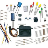
KIT WHAT'S A MICRO:PARTS ONLY
Manufacturer
Parallax Inc
Datasheet
1.28123.pdf
(340 pages)
Specifications of 28122
Accessory Type
Parts Kit
Product
Microcontroller Accessories
Core Processor
PIC16C57c
Flash
128 Bytes
Operating Supply Voltage
9 V
Board Size
31 mm x 16 mm
For Use With/related Products
Board of Education Full Kit
Lead Free Status / RoHS Status
Lead free / RoHS Compliant
- Current page: 88 of 340
- Download datasheet (6Mb)
Your Turn – A Pushbutton with a Pull-up Resistor
The circuit you just finished working with has a resistor connected to Vss. This resistor
is called a pull-down resistor because it pulls the voltage at P3 down to Vss (0 volts)
when the button is not pressed. Figure 3-9 shows a pushbutton circuit that uses a pull-up
resistor. This resistor pulls the voltage up to Vdd (5 volts) when the button is not
pressed. The rules are now reversed. When the button is not pressed,
number 1, and when the button is pressed,
P3
√
√
√
220
The 220 Ω resistor is used in the pushbutton example circuits to protect the BASIC Stamp
I/O pin. Although it’s a good practice for prototyping, in most products, this resistor is
replaced with a wire (since wires cost less than resistors).
Modify your circuit as shown in Figure 3-9.
Re-run ReadPushbuttonState.bs2.
Using the Debug Terminal, verify that
and 0 when the button is pressed.
Active-low vs. Active-high: This pushbutton Figure 3-9 is called active-low because it
sends the BASIC Stamp a low signal (Vss) when the button is active (pressed).
pushbutton circuit in Figure 3-6 the main activity is active-high because it sends a high
signal (Vdd) when the button is active (pressed).
Ω
Vdd
Vss
10
kΩ
P15
P14
P13
P12
P11
P10
P9
P8
P7
P6
P5
P4
P3
P2
P1
P0
X2
X3
Vdd
IN3
Vin
stores the number 0.
IN3
Vss
is 1 when the button is not pressed
Figure 3-9
Modified Pushbutton
Circuit
IN3
stores the
The
Related parts for 28122
Image
Part Number
Description
Manufacturer
Datasheet
Request
R

Part Number:
Description:
Microcontroller Modules & Accessories DISCONTINUED BY PARALLAX
Manufacturer:
Parallax Inc

Part Number:
Description:
BOOK UNDERSTANDING SIGNALS
Manufacturer:
Parallax Inc
Datasheet:

Part Number:
Description:
COMPETITION RING FOR SUMOBOT
Manufacturer:
Parallax Inc
Datasheet:

Part Number:
Description:
TEXT INFRARED REMOTE FOR BOE-BOT
Manufacturer:
Parallax Inc
Datasheet:

Part Number:
Description:
BOARD EXPERIMENT+LCD NX-1000
Manufacturer:
Parallax Inc
Datasheet:

Part Number:
Description:
CONTROLLER 16SERVO MOTOR CONTROL
Manufacturer:
Parallax Inc
Datasheet:

Part Number:
Description:
BASIC STAMP LOGIC ANALYZER
Manufacturer:
Parallax Inc
Datasheet:

Part Number:
Description:
IC MCU 2K FLASH 50MHZ SO-18
Manufacturer:
Parallax Inc
Datasheet:


