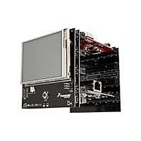
TWR-LCD Freescale Semiconductor, TWR-LCD Datasheet - Page 7

TWR-LCD
Manufacturer Part Number
TWR-LCD
Description
LCD MODULE FOR TWR SYSTEM
Manufacturer
Freescale Semiconductor
Specifications of TWR-LCD
Accessory Type
LCD Display
Product
Microcontroller Modules
Data Bus Width
32 bit
Core Processor
MCF51JM
Interface Type
USB, I2C, SPI
Operating Supply Voltage
5 V
Silicon Manufacturer
Freescale
Core Architecture
Coldfire
Core Sub-architecture
Coldfire V1
Silicon Core Number
MCF51
Silicon Family Name
Flexis - MCF51AC, MCF521x, MCF5301x
Rohs Compliant
Yes
For Use With/related Products
Freescale Tower System
Lead Free Status / RoHS Status
Lead free / RoHS Compliant
3.3 MicroSD Card
The Tower System defines a Secure Digital interface as shown in 0. The SD Card interface is multiplexed
over the SPI1 signals and two GPIOs such that the host can communicate with the SD memory card in
the SD Card slot using the SPI mode or the one‐ or four‐bit SD mode.
The MicroSD Card slot is accessible to either the on‐board MCF51JM MCU or a compatible Tower MCU
Module. Use SW1 –DIP4 to select which MCU has access to the MicroSD Card slot. Refer to Section 4
for more configuration details.
Setting the EuSD (SW1‐DIP4) configuration switch to the “Off” position will isolate the SD signals from
the Tower MCU allowing a direct connection between the on‐board MCF51JM MCU and the MicroSD
Card slot.
Setting the EuSD configuration switch to the “On” position will cause both the on‐board MCF51JM
MCU and Tower MCU SD signals to be simultaneously connected to the MicroSD Card slot. It is
required that on‐board MCF51JM MCU firmware detects the status of the EuSD signal and tri‐state the
on‐board MCF51JM MCU SD signals.
The SD Card Detect signal is connected to KBI7 on the on‐board MCF51JM MCU and, if configured via
EuSD (SW1‐DIP4), IRQ_H on the Primary Tower Elevator. This will allow the host controller to monitor
the presence of an SD memory card. To ensure that he SD Card Detect is handled properly, the
MCF51JM must configure the SD Card Detect GPIO/KBI (PTG3 / KBIP7) as an internal pull‐up. This is
done by setting the appropriate register values for PTEPE (PTGPE3=1) for GPIO and additionally KBI1ES
SW5-DIP 4
Elevator
Pin #
A10
B10
B11
B22
B7
B9
(SW1-DIP4)
ELE uSD
SDHC_CMD / SPI1_MOSI
Isolation (YMNS)
Touch Panel
Isolation (YPLS)
SDHC_D3 / SPI1_CS0_b
SDHC_D0 / SPI1_MISO
SDHC_CLK / SPI1_CLK
GPIO2 / SDHC_D1
GPIO8 / SDHC_D2
Name
OFF
ON
Table 7 ‐ Tower System SD Card Interface Pinout
Table 6 ‐ MicroSD Card Slot MCU Selection
MicroSD is connected to the SPI1 of Primary Elevator Connector
MicroSD is connected to the on-board MCF51JM MCU
OFF
OFF
ON
GPIO / SDHC
GPIO / SDHC
SDHC / SPI 1
SDHC / SPI 1
SDHC / SPI 1
SDHC / SPI 1
TWR‐LCD User’s Manual
Group
Connects AN7 (TWR-ELEV) to YPLS Touch Panel Signal
Disconnects AN6 from Touch Panel
Disconnects AN7 from Touch Panel
General Purpose I/O or SDHC Data
General Purpose I/O or SDHC Data
SDHC Command or SPI Master Out / Slave In
SDHC Chip Select / Data or SPI Chip Select
SDHC Data or SPI Master In / Slave Out
SDHC or SPI Clock
Description
Page 7 of 13
I/O
I/O
I/O
O
O
O
I


