AC164337 Microchip Technology, AC164337 Datasheet - Page 44
AC164337
Manufacturer Part Number
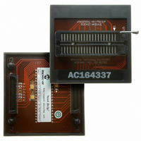
AC164337
Description
MODULE SOCKET FOR PM3 40DIP
Manufacturer
Microchip Technology
Datasheet
1.AC164335.pdf
(286 pages)
Specifications of AC164337
Module/board Type
Socket Module - DIP
Product
Microcontroller Accessories
Lead Free Status / RoHS Status
Not applicable / Not applicable
For Use With/related Products
MPLAB® PM3
Lead Free Status / RoHS Status
Lead free / RoHS Compliant, Not applicable / Not applicable


dsPIC30F1010/202X
4.1.2
The three-operand MCU instructions are of the form:
where Operand 1 is always a working register (i.e., the
Addressing mode can only be register direct), which is
referred to as Wb. Operand 2 can be a W register,
fetched from data memory, or a 5-bit literal. The result
location can be either a W register or an address
location. The following Addressing modes are
supported by MCU instructions:
• Register Direct
• Register Indirect
• Register Indirect Post-modified
• Register Indirect Pre-modified
• 5-bit or 10-bit Literal
4.1.3
Move instructions and the DSP Accumulator class of
instructions provide a greater degree of addressing
flexibility than other instructions. In addition to the
Addressing modes supported by most MCU instruc-
tions, move and accumulator instructions also support
Register Indirect with Register Offset Addressing
mode, also referred to as Register Indexed mode.
In summary, the following Addressing modes are
supported by move and accumulator instructions:
• Register Direct
• Register Indirect
• Register Indirect Post-modified
• Register Indirect Pre-modified
• Register Indirect with Register Offset (Indexed)
• Register Indirect with Literal Offset
• 8-bit Literal
• 16-bit Literal
DS70178C-page 42
Note:
Note:
Note:
Operand 3 = Operand 1 <function> Operand 2
MCU INSTRUCTIONS
Not all instructions support all the
Addressing modes given above. Individual
instructions may support different subsets
of these Addressing modes.
MOVE AND ACCUMULATOR
INSTRUCTIONS
For the MOV instructions, the Addressing
mode specified in the instruction can differ
for the source and destination EA. How-
ever, the 4-bit Wb (Register Offset) field is
shared
destination (but typically only used by
one).
Not all instructions support all the
Addressing modes given above. Individual
instructions may support different subsets
of these Addressing modes.
between
both
source
and
Preliminary
4.1.4
The dual source operand DSP instructions (CLR, ED,
EDAC, MAC, MPY, MPY.N, MOVSAC and MSC), also
referred to as MAC instructions, utilize a simplified set of
Addressing modes to allow the user to effectively
manipulate the data pointers through register indirect
tables.
The two source operand prefetch registers must be a
member of the set {W8, W9, W10, W11}. For data
reads, W8 and W9 will always be directed to the X
RAGU and W10 and W11 will always be directed to the
Y AGU. The effective addresses generated (before and
after modification) must, therefore, be valid addresses
within X data space for W8 and W9 and Y data space
for W10 and W11.
In summary, the following Addressing modes are
supported by the MAC class of instructions:
• Register Indirect
• Register Indirect Post-modified by 2
• Register Indirect Post-modified by 4
• Register Indirect Post-modified by 6
• Register Indirect with Register Offset (Indexed)
4.1.5
Besides the various Addressing modes outlined above,
some instructions use literal constants of various sizes.
For example, BRA (branch) instructions use 16-bit
signed literals to specify the branch destination directly,
whereas the DISI instruction uses a 14-bit unsigned
literal field. In some instructions, such as ADD Acc, the
source of an operand or result is implied by the opcode
itself. Certain operations, such as NOP, do not have any
operands.
Note:
MAC INSTRUCTIONS
Register Indirect with Register Offset
Addressing is only available for W9 (in X
space) and W11 (in Y space).
OTHER INSTRUCTIONS
© 2006 Microchip Technology Inc.
Related parts for AC164337
Image
Part Number
Description
Manufacturer
Datasheet
Request
R

Part Number:
Description:
Manufacturer:
Microchip Technology Inc.
Datasheet:
Part Number:
Description:
Manufacturer:
Microchip Technology Inc.
Datasheet:
Part Number:
Description:
Manufacturer:
Microchip Technology Inc.
Datasheet:
Part Number:
Description:
Manufacturer:
Microchip Technology Inc.
Datasheet:
Part Number:
Description:
Manufacturer:
Microchip Technology Inc.
Datasheet:
Part Number:
Description:
Manufacturer:
Microchip Technology Inc.
Datasheet:
Part Number:
Description:
Manufacturer:
Microchip Technology Inc.
Datasheet:
Part Number:
Description:
Manufacturer:
Microchip Technology Inc.
Datasheet: