AC164127-6 Microchip Technology, AC164127-6 Datasheet - Page 59
AC164127-6
Manufacturer Part Number
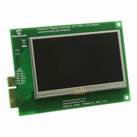
AC164127-6
Description
BOARD 4.3" LCD TOUCH SCREEN
Manufacturer
Microchip Technology
Datasheet
1.AC164127-6.pdf
(64 pages)
Specifications of AC164127-6
Main Purpose
Displays, LCD Display
Primary Attributes
4.3" WQVGA, Touch Screen
Secondary Attributes
Parallel Interface
Lead Free Status / RoHS Status
Lead free / RoHS Compliant
For Use With
AC164127-5 - BOARD GRAPH LCD CNTLR PICTAIL
Utilized Ic / Part
-
Embedded
-
Lead Free Status / Rohs Status
Lead free / RoHS Compliant
Available stocks
Company
Part Number
Manufacturer
Quantity
Price
Company:

Part Number:
AC164127-6
Manufacturer:
Microchip Technology
Quantity:
135


Appendix B. Modifications for PICtail Plus Daughter Boards
B.1
B.2
2010 Microchip Technology Inc.
INTRODUCTION
OVERVIEW OF THE PICTAIL PLUS INTERFACE
This appendix provides a detailed description of the modifying the development board
for use with different PICtail Plus daughter boards. Topics include:
• Overview of the PICtail Plus Interface
• Modifications for Specific Daughter Boards
To maximize their versatility, many of Microchip’s development and demonstration
boards are equipped with the PICtail Plus interface. This allows boards with a standard-
ized edge connector to directly access the I/O lines of each other’s microcontrollers and
expand their functionality. In most cases, this is used to allow a more fully-featured
board (such as the PIC24FJ256DA210 Development Board) to connect to a PICtail
Plus daughter card and add new features to a pretape application (for example, adding
100 Mbps Ethernet using the Fast 100 Mbps Ethernet Daughter Board).
The basis for the design of the PICtail Plus interface is Microchip’s adherence to a stan-
dard migration pathway throughout its microcontroller families: that is, for a given
microcontroller package pin count, certain I/O ports are always located on specific pins
of the PICtail Plus interface, and specific peripherals are almost always associated with
specific I/O ports. This permits daughter boards to use a specific pin for SPI communi-
cation, for example, because microcontrollers will always have an SPI peripheral asso-
ciated with that I/O pin, and that PICtail Plus connector pin.
There are exceptions, however. Because of its complex graphics interface and
enhanced PMP, the PIC24FJ256DA210 microcontroller does not map I/O ports and
peripherals in the same way as other 100-pin devices are mapped. To maximize com-
patibility, this requires a change of the PICtail Plus mapping for the PIC24FJ256DA210
Development Board. The complete mapping from microcontroller to interface are
shown in Table B-1.
Since PICtail Plus-compatible daughter boards are designed to the standard interface,
some additional remapping of the interface is needed to make the PIC24FJ256DA210
Development Board compatible. Provisions to do this are made by connecting a group
of I/O lines the resistor bank described in Section 4.4.6 “PICtail™ Plus Card Modular
Expansion Connector”. Populating or removing specific resistors in this bank allows
the remapping of certain signals and restoring compatibility with specific daughter
boards. As of this writing, the development board can be made compatible with all
available PICtail Plus daughter boards.
A list of specific signals controlled by the resistor bank is provided in Table B-2; note
that some signals are routed to multiple pins on the PICtail Plus interface by default to
maximize compatibility. Table B-3 shows the same information to specifically highlight
which signals can be remapped to a particular pin.
Section B.3 “Modifications for Specific Daughter Boards” describes the specific
resistor changes required for each PICtail Plus daughter board.
DEVELOPMENT BOARD
PIC24FJ256DA210
USER’S GUIDE
DS51911A-page 59
Related parts for AC164127-6
Image
Part Number
Description
Manufacturer
Datasheet
Request
R

Part Number:
Description:
Fuses 16A 415V AC/250V DC
Manufacturer:
Apex Tool Group (Formerly Cooper Tools)

Part Number:
Description:
Manufacturer:
Microchip Technology Inc.
Datasheet:
Part Number:
Description:
Manufacturer:
Microchip Technology Inc.
Datasheet:
Part Number:
Description:
Manufacturer:
Microchip Technology Inc.
Datasheet:
Part Number:
Description:
Manufacturer:
Microchip Technology Inc.
Datasheet:
Part Number:
Description:
Manufacturer:
Microchip Technology Inc.
Datasheet:
Part Number:
Description:
Manufacturer:
Microchip Technology Inc.
Datasheet:
Part Number:
Description:
Manufacturer:
Microchip Technology Inc.
Datasheet:
Part Number:
Description:
Manufacturer:
Microchip Technology Inc.
Datasheet: