ADISUSBZ Analog Devices Inc, ADISUSBZ Datasheet
ADISUSBZ
Specifications of ADISUSBZ


Related parts for ADISUSBZ


ADISUSBZ Summary of contents
Page 1
... Documentation CD Note product is listed twice, it can be run at +3.3 or +5V. Step #6 - Launch evaluation software Hook the ADISUSBZ to the USB cable and then launch the evaluation software by double clicking on its *.exe file. The program will also be in the Start Programs menu in Windows. Figure 15 though Figure 21 offers some basic insights into the operation of each product’ ...
Page 2
... ADISUSBZ Figure 2. Installation Launch Screen (click on computer button) Figure 1. Installation Welcome Screen (Click OK) Rev. PrA | Page Preliminary Technical Data ...
Page 3
Preliminary Technical Data Figure 3. Program Group Menu (Click Continue) Rev. PrA | Page ADISEVAL/USBZ ...
Page 4
... ADISUSBZ Figure 6. Giveio.exe Installation Confirmation Menu (Click Yes) Figure 4. Giveio.exe Installation Screen (Click Install) Figure 5. Giveio.exe License Agreement (Click I Agree) Rev. PrA | Page Preliminary Technical Data ...
Page 5
Preliminary Technical Data Figure 8 .USB Driver Hardware Installation (Click on Continue Anyway) Figure 7. USB Driver Installation (Click Next) Rev. PrA | Page ADISEVAL/USBZ ...
Page 6
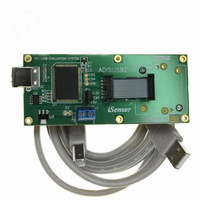
... ADISUSBZ Figure 9. Installing the ADIS16xxx/PCBZ onto the ADISUSBZ Figure 10. ADIS16xxx/PCBZ Installed View Rev. PrA | Page Preliminary Technical Data ...
Page 7
... Preliminary Technical Data Figure 11. Installing ADIS1635xAMLZ onto the ADISUSBZ Figure 12. ADIS1635xAMLZ Installed View Rev. PrA | Page ADISEVAL/USBZ ...
Page 8
... ADISUSBZ Figure 13 – iSensor Figure 14 – iSensor ® ADISUSBZ Interface Board Layout (Top View) ® ADISUSBZ Interface Board Layout (Bottom View) Rev. PrA | Page Preliminary Technical Data ...
Page 9
Preliminary Technical Data FIGURE FLAG NOTES: 1. Set the Device type to ADIS16003 or ADIS16006. Set the Interface to parallel and set the port address per ReadMeFirst.PDF 2. Set the axis being tested. Test function exercises a ...
Page 10
... ADISUSBZ FIGURE FLAG NOTES: 1. Set the Device type to ADIS16080 or ADIS16100. Set the Interface to parallel and set the port address per ReadMeFirst.PDF 2. Set the output channel being tested. Test function exercises a self-test during a single sweep on the screen. 3. Plot and log data to files. ...
Page 11
Preliminary Technical Data FIGURE FLAG NOTES: 1. Perform a single read of the ADIS16201’s output data 2. Start and stop continuous reading of the ADIS16201’s output data. Set the acquisition loop delay time. This provides rough control ...
Page 12
... ADISUSBZ FIGURE FLAG NOTES: 1. Perform a single read of the ADIS16203’s output data 2. Start and stop continuous reading of the ADIS16203’s output data. Set the acquisition loop delay time. This provides rough control over sample times. Please note that this data will not have a high degree of coherence. ...
Page 13
Preliminary Technical Data FIGURE FLAG NOTES: 1. Perform a single read of the ADIS16209’s output data 2. XINCL_OUT and YINCL_OUT are horizontal incline outputs. ROTATION is the vertical-oriented rotational position measurement. This requires the X and ...
Page 14
... ADISUSBZ 6 1 FIGURE FLAG NOTES: 1. Perform a single read of the ADIS1625x’s output data 2. Start and stop continuous reading of the ADIS1625x’s output data. Set the acquisition loop delay time. This provides rough control over sample times. Please note that this data will not have a high degree of coherence. ...
Page 15
Preliminary Technical Data FIGURE FLAG NOTES: 1. Perform a single read of the ADIS1635x’s output data. Also select “Loop” checkbox for continuous data scroll across the screen. Use the Loop delay box to add delay between ...