STM3210B-MCKIT STMicroelectronics, STM3210B-MCKIT Datasheet
STM3210B-MCKIT
Specifications of STM3210B-MCKIT


Related parts for STM3210B-MCKIT


STM3210B-MCKIT Summary of contents
Page 1
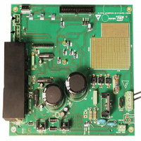
... This manual describes where the various components are located on the motor control board, and the appropriate settings for driving a PMSM motor induction motor. The MB459B board is delivered with the STM3210B-MCKIT and STR750-MCKIT motor control kits. For more information on these kits, December 2007 ...
Page 2
Contents Contents 1 Hardware layout . . . . . . . . . . . . . . . . . . . . . . . . . . . . . . . . . . . ...
Page 3
... J1 connector: auxiliary supply input 5. J8 connector: Hall sensors / encoder input 6. J6 connector: tachometer input for closed-loop controlled AC motors 7. J5 connector: Three-phase output to motor 8. J7 motor connector: link to STR75x and to STM3210B-EVAL evaluation board, or other control board 9. 7A inverter and level shifter ...
Page 4
Power supply 2 Power supply The MB459B motor control evaluation board can be supplied from a single power supply or from a dual power supply. ● Single power supply for motors requiring a voltage greater than 18 V The power ...
Page 5
UM0379 3 Operational amplifier configuration The MB459B motor control evaluation board can be configured to run in two current reading configuration modes: ● Three-shunt configuration ● Single-shunt configuration Single-shunt configuration requires a single op-amp, three-shunt configuration requires three op-amps, and ...
Page 6
Operational amplifier configuration The op-amp is used in follower mode with a gain set by resistors r and r)/r The relation between the input signal e and the signal v on ...
Page 7
UM0379 3.2 Single-shunt current reading configuration In the single-shunt current reading configuration, the current sampling is done only when the value on the shunt resistor is positive. The only positive value read on the shunt resistor allows to set a ...
Page 8
Operational amplifier configuration The response of the op-amp is shown in Figure 6. Voltage response in single-shunt configuration 3.500 3.000 2.500 2.000 1.500 1.000 0.500 0.000 0 In this configuration, the output voltage of the op-amp is equal to 3.16V ...
Page 9
UM0379 3.3 Jumper configuration Based on the two current reading configurations for single-shunt and three-shunt, the final configuration of the common op-amp is summarized in Figure 7. Common op-amp configuration e shunt U Operational amplifier configuration Figure W8 1_Shunt W7 ...
Page 10
Electrical specifications 4 Electrical specifications Table 1 provides the maximum ratings for the MB459B motor control board. Table 1. Motor control evaluation board electrical specifications Motor types Main input voltage (J3) Auxiliary input voltage (J1) Maximum output current on motor ...
Page 11
... The MB469B STR75x evaluation board provided in the STR750-MCKIT or the STM3210B-EVAL evaluation board provided with the STM3210B-MCKIT are perfectly suited for this task. To drive any other generic high voltage PMSM motor, you must ensure that: ● ...
Page 12
Hardware settings for driving AC induction motors 6 Hardware settings for driving AC induction motors To drive an AC induction motor, you must ensure that: ● The motor control evaluation board is driven by an adapted control board that outputs ...
Page 13
UM0379 7 Description of jumper and connector settings Table 4. Jumper descriptions Jumper “ HIGH VOLTAGE” “< 35V Only” W1 Not present Present W4 Not present Present W5 Not present Present W6 Not present Set to default position of silk-screen ...
Page 14
Description of jumper and connector settings Table 4. Jumper descriptions (continued) Jumper Present W11 Not present Present W12 Not present Present W13 Not present Present W14 Not present Present W15 Not present Set to default position of silk-screen printing W16 ...
Page 15
UM0379 Table 5. Connector pinout descriptions Name Reference Description of jumper and connector settings Optional 15V DC, 0.5A input connector to supply the motor ...
Page 16
Description of jumper and connector settings Table 5. Connector pinout descriptions (continued) Name Reference 16/21 Description/pinout Motor control connector 1) EMERGENCY STOP ---------------- 2) GND 3) PWM-1H ---------------------------------- 4) GND 5) PWM-1L ---------------------------------- 6) GND 7) PWM-2H ...
Page 17
... The value of resistors R13, R23 and R52 has decreased from 2.2kΩ to 1.8kΩ. ● The D3 diode is now short-circuited. ● The board can also be driven by the STM3210B-EVAL board. (Figure 8), shows the op-amp wiring and (Figure 9), shows the power converter with its associated level ...
Page 18
Schematic diagrams Figure 8. Schematics sheet 1/2: current measurement 4K7 R76 4K7 R77 4K7 R78 14 4K7 R82 4K7 R81 4K7 R80 ENCODER / SENSOR HALL 4 1 18/ METER TACHO 14 7 UM0379 ...
Page 19
UM0379 Figure 9. Schematics sheet 2/2: power switch soldered Schematic diagrams 1 3 Board BEMF_Daughter 3 GND 1 19/21 ...
Page 20
Revision history 9 Revision history Table 6. Document revision history Date 7-Feb-2007 17-Dec-2007 20/21 Revision 1 Initial release. Added list of changes to the MB459B board compared with the previous version in Section 8: Schematic 2 Update for release of ...
Page 21
... UM0379 Information in this document is provided solely in connection with ST products. STMicroelectronics NV and its subsidiaries (“ST”) reserve the right to make changes, corrections, modifications or improvements, to this document, and the products and services described herein at any time, without notice. All ST products are sold pursuant to ST’s terms and conditions of sale. ...