MCP73113EV-1SOVP Microchip Technology, MCP73113EV-1SOVP Datasheet - Page 12
MCP73113EV-1SOVP
Manufacturer Part Number
MCP73113EV-1SOVP
Description
BOARD EVAL BATT CHARGER MCP73113
Manufacturer
Microchip Technology
Type
Battery Managementr
Datasheet
1.MCP73113EV-1SOVP.pdf
(22 pages)
Specifications of MCP73113EV-1SOVP
Main Purpose
Power Management, Battery Charger
Embedded
No
Utilized Ic / Part
MCP73113
Primary Attributes
1 Cell- Li-Ion / Li-Pol, 4.2V @ 500mA
Secondary Attributes
Safety Timer, Thermal Protection, Automatic Charge Termination and Recharge
Input Voltage
4.2 V to 6.5 V
Maximum Operating Temperature
+ 85 C
Minimum Operating Temperature
- 40 C
Operating Supply Voltage
4.2 V to 6.5 V
Product
Power Management Modules
Supply Current
4 uA
Silicon Manufacturer
Microchip
Silicon Core Number
MCP73113, MCP73114
Kit Application Type
Power Management - Battery
Application Sub Type
Battery Charger
Kit Contents
Board
For Use With/related Products
MCP73113
Lead Free Status / RoHS Status
Lead free / RoHS Compliant
Lead Free Status / RoHS Status
Lead free / RoHS Compliant, Lead free / RoHS Compliant


MCP73113 OVP Single-Cell Li-Ion Battery Charger Evaluation Board User’s Guide
2.3
DS51847A-page 8
GETTING STARTED
The MCP73113 OVP Single-Cell Li-Ion Battery Charger Evaluation Board is fully
assembled and tested for charging a single-cell Li-Ion or Li-Polymer battery.
2.3.1
2.3.1.1
1. Connect the positive battery terminal to V
2. Connect the 5V DC power supply Negative Terminal to V
3. Connect the 5V DC power supply Positive Terminal to V
4. It should initiate the battery charging cycle when the power source is present and
5. The charging status table is available in Table 2-2.
6. The fast charge current is preset at 500 mA and can be increased to 1A by
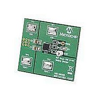
FIGURE 2-1:
Note:
Note:
5V DC SUPPLY
V
V
to be lower than 3.99V to initiate the charge cycle.
connecting PROG via to ground.
BAT-
BAT
.
is below recharge threshold. For example, when V
BATTERY
Power Input and Output Connection
POWERING THE MCP73113 OVP SINGLE-CELL LI-ION BATTERY
CHARGER EVALUATION BOARD
The Li-Ion battery pack can be replaced with test circuit or electronic load
that can sink current with DC power supply. Refer to Figure 2-3.
Fast Charge Current can be programmed with various resistors based on
Figure 2-2 and Table 2-1.
LI-ION
1-CELL
+
-
+
-
Board Top Assembly.
BAT+
and negative battery terminal to
© 2009 Microchip Technology Inc.
REG
DD
SS
.
.
is 4.2V, V
BAT
needs
1
Related parts for MCP73113EV-1SOVP
Image
Part Number
Description
Manufacturer
Datasheet
Request
R

Part Number:
Description:
Manufacturer:
Microchip Technology Inc.
Datasheet:
Part Number:
Description:
Manufacturer:
Microchip Technology Inc.
Datasheet:
Part Number:
Description:
Manufacturer:
Microchip Technology Inc.
Datasheet:
Part Number:
Description:
Manufacturer:
Microchip Technology Inc.
Datasheet:
Part Number:
Description:
Manufacturer:
Microchip Technology Inc.
Datasheet:
Part Number:
Description:
Manufacturer:
Microchip Technology Inc.
Datasheet:
Part Number:
Description:
Manufacturer:
Microchip Technology Inc.
Datasheet:
Part Number:
Description:
Manufacturer:
Microchip Technology Inc.
Datasheet: