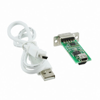
MCP2200EV-VCP Microchip Technology, MCP2200EV-VCP Datasheet - Page 12

MCP2200EV-VCP
Manufacturer Part Number
MCP2200EV-VCP
Description
MOD EVAL USB/RS232 MCP2200
Manufacturer
Microchip Technology
Datasheets
1.MCP2200-IMQ.pdf
(34 pages)
2.MCP2200-IMQ.pdf
(4 pages)
3.MCP2200EV-VCP.pdf
(36 pages)
4.MCP2200EV-VCP.pdf
(20 pages)
Specifications of MCP2200EV-VCP
Design Resources
MCP2200EV-VCP Schematic and PCB
Main Purpose
Interface, USB 2.0 to UART (RS232) Bridge
Embedded
No
Utilized Ic / Part
MCP2200
Primary Attributes
Full Speed (12Mbps)
Secondary Attributes
LED Status Indicators
Processor To Be Evaluated
MCP2200
Processor Series
MCP2200
Interface Type
RS-232, USB
Operating Supply Voltage
3 V to 5.5 V
Silicon Manufacturer
Microchip
Silicon Core Number
MCP2200
Kit Application Type
Interface
Application Sub Type
USB To RS232
Kit Contents
Board, Docs
Tool Type
Demonstration Board
Core Architecture
PIC
Cpu Core
PIC
Data Bus Width
8 bit
Lead Free Status / RoHS Status
Lead free / RoHS Compliant
Lead Free Status / RoHS Status
Lead free / RoHS Compliant, Lead free / RoHS Compliant
Available stocks
Company
Part Number
Manufacturer
Quantity
Price
Company:
Part Number:
MCP2200EV-VCP
Manufacturer:
LT
Quantity:
910
Part Number:
MCP2200EV-VCP
Manufacturer:
MICROCHIP/微芯
Quantity:
20 000
2.3
DS51901A-page 12
OPERATION
The board will operate as a USB to RS-232 converter. In addition, the accompanying
software can be used to control the I/O and set custom configurations.
2.3.1
The board can be connected to a USB host and to an RS-232 port that usually connects
to a PC. If the host application software sends a “Set Line Coding” command (sets the
UART baud rate), the MCP2200 will automatically change to the correct baud rate.
FIGURE 2-2:
2.3.2
The PC software allows the user to evaluate the functionality and set custom
configurations. Figure 2-3 shows the main screen.
The software aids in the development of custom configurations. The following can be
modified:
Vendor ID (VID) and Product ID (PID): The default VID is 0x04D8, which is assigned
to Microchip by the USB IF. The VID can be changed to another VID if authorized by
the owner of the assignment. Contact the USB IF for more information.
The default PID for the MCP2200 is 0x00DF and can be used ‘as-is’. Microchip's VID
can be sublicensed by obtaining a new PID from Microchip. See the product page or
board page for a link to the sublicensing agreement. Sublicensing is only required if
Microchip’s VID is used. Changing the VID to another assigned and authorized VID
does not require any sublicensing from Microchip.
Baud Rate: A pull-down box allows selection of the most commonly used baud rates.
I/O Config: It is a binary 8-bit value that configures the I/O port to input (logic ‘1’) or
output (logic ‘0’).
Output Default: It is the default value for the port pins configured as output. This is also
an 8-bit binary value.
Tx/Rx LEDs: Checking this box enables the LED functions on GP6 and GP7. The “LED
Function” and “Blink Duration” must be configured.
Hardware Flow Control: Enables the RTS and CTS pins for UART handshaking.
USBCFG Pin: Enables the USBCFG pin on GP1.
Suspend Pin: Enables the SSPND pin functionality on GP0.
UART Polarity: Enables the inverse polarity for the UART pins.
String Descriptors: Here you can enter custom Manufacturer and Product string
descriptors.
Update VID/PID Button: This button updates the software to use the VID and PID in
the “New” boxes. For example, if the PID was changed to 0xFFFF, the software would
keep using the original 0x00DF until the Update VID/PID button was pressed. After
this, the software would switch to the 0xFFFF PID.
USB to RS-232 Operation
Configuration Software
D-SUB 9-PIN MALE CONNECTOR
1
6
RXD
2
RTS CTS
7
TXD
3
8
4
9
GND
5
2010 Microchip Technology Inc.


