APGRD004 Microchip Technology, APGRD004 Datasheet - Page 4
APGRD004
Manufacturer Part Number
APGRD004
Description
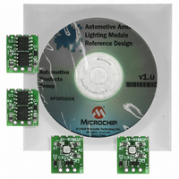
REF DESIGN MOD AUTO AMBNT LIGHT
Manufacturer
Microchip Technology
Specifications of APGRD004
Main Purpose
Lighting, RGB LED Controller
Embedded
Yes, MCU, 8-Bit
Utilized Ic / Part
MCP2021, PIC12F615
Primary Attributes
4 Tiny Boards, Each Have: RGB LED, LIN Transceiver, Voltage Regulator, MCU
Secondary Attributes
LIN Commands are Interpreted to Control 16,383 Colors and 1,023 Dimming Levels
Silicon Manufacturer
Microchip
Silicon Core Number
APGDT001
Kit Contents
4 Ambient Lighting Modules, Documentation
Lead Free Status / RoHS Status
Lead free / RoHS Compliant
Available stocks
Company
Part Number
Manufacturer
Quantity
Price
Company:

Part Number:
APGRD004
Manufacturer:
MICROCHIP
Quantity:
12 000


Driving LEDs with a Charge Pump
A charge pump power supply does not have inductors that
are required in other SMPS topologies. This provides a
more compact and less expensive circuit. The downside is
that charge pumps cannot supply large amounts of current
compared to the other topologies. Charge pump circuits
are most useful for backlighting applications. Common
applications include PCs, LCD displays and automotive
instrumentation.
MCP1252 Charge Pump Backlight
Demonstration Board
provides an enable signal to the MCP1252 and accepts a
push-button input that allows the white LEDs to be adjusted
to five different light intensities.
Literature on the Web
■
■
■
■
Charge Pump LED Driver Using the MCP1252
4
LED Lighting Solutions
MCP1252/3 Data Sheet, DS21572
MCP1252 Charge Pump Backlight Demo Board
User’s Guide, DS51551
MCP1252/3 Evaluation Kit User’s Guide, DS51313
DG10 – Power Solutions Design Guide, DS21913
LED Lighting Solutions Design Guide
PWM Brightness
Control
Single
Li-Ion
Cen
(MCP1252DM-BKLT)
Demonstrates the use of a charge
pump device in an LED application
and acts as a platform to evaluate
the MCP1252 device in general.
Light intensity is controlled
uniformly through the use of ballast
resistors. A PIC10F206 MCU
3
7
1
SHDN
PG
V
MCP1252-ADJ
5
IN
C-
GND
C+
V
OUT
FB
6
MCP1640 Single Cell Synchronous Boost Regulator
Driving LEDs with a Boost Regulator
A boost regulator topology is used when the output voltage
of the converter must be equal to or greater than the input
voltage. A boost regulator is useful for driving a chain of
LEDs connected in series. It is beneficial to drive multiple
LEDs in series. This ensures that all LEDs receive the same
amount of current and will have the same brightness level.
Using a coupled inductor in the boost circuit reducing the
switching voltage requirements of the MOSFET switch.
The MCP1640 synchronous boost regulator can provide
a stable operating voltage for an LED from a single cell
alkaline battery.
The MCP1650 Boost Regulator uses an external switch
so that it can be used for any type of load. An additional
advantage of the MCP1650 in battery applications is the
Gated Oscillator Architecture which provides 2 duty cycles
reducing high-peak inductor current and output ripple
voltages. Input voltages above 3.8V engage a 56% duty
cycle and an 80% duty cycle when the input voltage drops
below 3.8V, extending battery life in these applications.
0.9V to 1.7V
2
8
4
V
IN
4.7 μF
C
IN
4.7 μH
L
1
V
EN
IN
MCP1640
SW
GND
V
V
OUT
FB
www.microchip.com/lighting
976 KΩ
562 KΩ
3.3V @ 100 mA
V
OUT
10 μF
C
OUT
Related parts for APGRD004
Image
Part Number
Description
Manufacturer
Datasheet
Request
R

Part Number:
Description:
Manufacturer:
Microchip Technology Inc.
Datasheet:
Part Number:
Description:
Manufacturer:
Microchip Technology Inc.
Datasheet:
Part Number:
Description:
Manufacturer:
Microchip Technology Inc.
Datasheet:
Part Number:
Description:
Manufacturer:
Microchip Technology Inc.
Datasheet:
Part Number:
Description:
Manufacturer:
Microchip Technology Inc.
Datasheet:
Part Number:
Description:
Manufacturer:
Microchip Technology Inc.
Datasheet:
Part Number:
Description:
Manufacturer:
Microchip Technology Inc.
Datasheet:
Part Number:
Description:
Manufacturer:
Microchip Technology Inc.
Datasheet: