MCP23X17EV Microchip Technology, MCP23X17EV Datasheet - Page 5
MCP23X17EV
Manufacturer Part Number
MCP23X17EV
Description
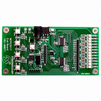
BOARD EVAL FOR MCP23X17
Manufacturer
Microchip Technology
Specifications of MCP23X17EV
Main Purpose
Interface, GPIO Expander
Embedded
Yes, MCU, 8-Bit
Utilized Ic / Part
MCP23017, MCP23S17
Primary Attributes
(2) 16-Bit GPIO Expanders, I2C and SPI
Secondary Attributes
4 Momentary Switches, 12 LEDs
Processor To Be Evaluated
MCP23x17
Data Bus Width
16 bit
Interface Type
SPI
Silicon Manufacturer
Microchip
Silicon Core Number
MCP23017, MCP23S17
Kit Application Type
Interface
Application Sub Type
GPIO Expander
Kit Contents
Board
Rohs Compliant
Yes
Lead Free Status / RoHS Status
Lead free / RoHS Compliant
Lead Free Status / RoHS Status
Lead free / RoHS Compliant, Lead free / RoHS Compliant
Available stocks
Company
Part Number
Manufacturer
Quantity
Price
Company:

Part Number:
MCP23X17EV
Manufacturer:
MICROCHIP
Quantity:
12 000


INTRODUCTION
DOCUMENT LAYOUT
© 2006 Microchip Technology Inc.
All documentation becomes dated, and this manual is no exception. Microchip tools and
documentation are constantly evolving to meet customer needs, so some actual dialogs
and/or tool descriptions may differ from those in this document. Please refer to our web site
(www.microchip.com) to obtain the latest documentation available.
Documents are identified with a “DS” number. This number is located on the bottom of each
page, in front of the page number. The numbering convention for the DS number is
“DSXXXXXA”, where “XXXXX” is the document number and “A” is the revision level of the
document.
This chapter contains general information that will be useful to know before using the
MCP23X17 Evaluation Board. Items discussed in this chapter include:
• Document Layout
• Conventions Used in this Guide
• Recommended Reading
• The Microchip Web Site
• Customer Support
• Document Revision History
This document describes how to use the MCP23X17 Evaluation Board as a develop-
ment tool to emulate and debug firmware on a target board. The manual layout is as
follows:
• Chapter 1. “Product Overview” – Important information about the MCP23X17
• Chapter 2. “Installation and Operation” – Includes instructions on how to get
• Appendix A. “Schematic and Layouts” – Shows the schematic and layout
• Appendix B. “Bill Of Materials (BOM)” – Lists the parts used to build the
Evaluation Board.
started with the MCP23X17 Evaluation Board.
diagrams for the MCP23X17 Evaluation Board.
MCP23X17 Evaluation Board.
NOTICE TO CUSTOMERS
Preface
MCP23X17 EVALUATION
BOARD USER’S GUIDE
DS51592B-page 1
Related parts for MCP23X17EV
Image
Part Number
Description
Manufacturer
Datasheet
Request
R

Part Number:
Description:
MCP2,8 RECEPTACLE CONTACT
Manufacturer:
TE Connectivity
Datasheet:

Part Number:
Description:
MCP2,8 BU-KONT EDS
Manufacturer:
TE Connectivity
Datasheet:

Part Number:
Description:
MCP2,8 BU-CONTACT EDS
Manufacturer:
Tyco Electronics
Datasheet:
Part Number:
Description:
MCP2,8 SOCKET CONT SWS
Manufacturer:
Tyco Electronics
Datasheet:
Part Number:
Description:
MCP2,8 BU-CONTACT EDS
Manufacturer:
Tyco Electronics
Datasheet:
Part Number:
Description:
MCP2,8 BU-CONTACT EDS
Manufacturer:
Tyco Electronics
Datasheet:
Part Number:
Description:
MCP2,8 BU-CONTACT EDS
Manufacturer:
Tyco Electronics
Datasheet:
Part Number:
Description:
MCP2,8 BU-CONTACT EDS
Manufacturer:
Tyco Electronics
Datasheet:
Part Number:
Description:
MCP2,8 BU-CONTACT EDS
Manufacturer:
Tyco Electronics
Datasheet:
Part Number:
Description:
MCP2,8 BU-CONTACT EDS
Manufacturer:
Tyco Electronics
Datasheet:

Part Number:
Description:
Manufacturer:
Microchip Technology Inc.
Datasheet:
Part Number:
Description:
Manufacturer:
Microchip Technology Inc.
Datasheet:
Part Number:
Description:
Manufacturer:
Microchip Technology Inc.
Datasheet: