MCP2140DM-TMPSNS Microchip Technology, MCP2140DM-TMPSNS Datasheet - Page 25
MCP2140DM-TMPSNS
Manufacturer Part Number
MCP2140DM-TMPSNS
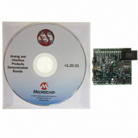
Description
BOARD DEMO FOR MCP2140
Manufacturer
Microchip Technology
Datasheets
1.MCP2140-ISO.pdf
(58 pages)
2.MCP2140-ISO.pdf
(6 pages)
3.MCP2140DM-TMPSNS.pdf
(52 pages)
Specifications of MCP2140DM-TMPSNS
Main Purpose
Interface, IrDA
Embedded
Yes, MCU, 8-Bit
Utilized Ic / Part
MCP2140
Primary Attributes
IrDA Controller with PIC18F MCU and Temp Sensor Temp
Secondary Attributes
Set up as a Data Logger
Processor To Be Evaluated
MCP2140
Interface Type
ICSP
Silicon Manufacturer
Microchip
Silicon Core Number
MCP2140
Kit Application Type
Sensing - Temperature
Application Sub Type
Temperature Sensor
Kit Contents
Board
Rohs Compliant
Yes
Lead Free Status / RoHS Status
Lead free / RoHS Compliant
Lead Free Status / RoHS Status
Lead free / RoHS Compliant, Lead free / RoHS Compliant
Other names
MCP2140DM-TMPSNSR
MCP2140DM-TMPSNSR
MCP2140DM-TMPSNSR
Available stocks
Company
Part Number
Manufacturer
Quantity
Price
Company:

Part Number:
MCP2140DM-TMPSNS
Manufacturer:
Microchip Technology
Quantity:
135
Company:
Part Number:
MCP2140DM-TMPSNS
Manufacturer:
MICROCHIP
Quantity:
12 000


2004 Microchip Technology Inc.
The key signals for the MCP2140-to-IR transceiver circuit are shown in Table 2-2.
Further information on the IR transceiver interface may be obtained from the MCP2140
data sheet (DS21790).
TABLE 2-2:
In addition to the signals described in Tables 2-1 and 2-2, the PHACT (Protocol Handler
Active) output signal indicates which mode the MCP2140 IrDA standard protocol
controller state machine is in (0 = NDM or Low-power mode,1 = Discovery or NRM)
and is connected to the PHACT LED (D4); the RESET input is connected to the RESET
output of the Host Controller (I/O pin RA4), which asserts low after the RESET
push-button switch is asserted; the RI (Ring Indicator) input is pulled to ground; and the
OSC1 and OSC2 pins are connected to an external 7.3728 MHz oscillator, as specified
in the MCP2140 data sheet (allowing the device to transmit at 9600 baud).
2.5.2.1
The MCP2140 (U3) implements the 9-wire “cooked” service class in the IrCOMM
application layer protocol of the IrDA standard specification. IrCOMM is the IrDA
standard specification for the replacement of the communication ports (serial and
parallel) of a PC. The MCP2140 allows the replacement of the serial cable with a wire-
less interface. The MCP2140 implements the entire protocol layer, and the Host
Controller (PIC18F1320) “talks” to the MCP2140 as if it were a serial port with flow
control.
The MCP2140 operates as a Secondary device only, so it will not initiate IrDA standard
communication with other IrDA standard devices (neither a Secondary device nor a
Primary device).
Appendix C. “MCP2140 Connection Sequence Overview” shows the connection
sequence between a Primary device and the MCP2140 (Secondary device). This
connection sequence is shown at an overview level and does not show exact
operation.
RXPDREF
TXIR
RXPD
Legend: A = Analog
Pin Name
I = Input
MCP2140 OPERATION
Number
(SSOP)
Pin
20
MCP2140 IR INTERFACE PINS
1
2
Type
Pin
O
I
I
Buffer
Type
—
A
A
IR Receive Photo Detect Diode reference voltage.
This voltage will typically be in the range of V
Asynchronous transmit to IrDA
transceiver.
IR RX Photo Detect Diode input. This input signal is
required to be a pulse to indicate an IR bit. When
the amplitude of the signal crosses the amplitude
threshold set by the RXPDREF pin, the IR bit is
detected. The pulse has minimum and maximum
requirements as specified in the MCP2140 data
sheet, Electrical Characteristics table,
Parameter IR131A.
P = Power
O = Output
Description
®
standard
DS51487A-page 21
DD
/2.
Related parts for MCP2140DM-TMPSNS
Image
Part Number
Description
Manufacturer
Datasheet
Request
R

Part Number:
Description:
IC IRDA CONTROLLR DTE/DCE 18SOIC
Manufacturer:
Microchip Technology
Datasheet:

Part Number:
Description:
The MCP2140 Embeds Irda Protocol Handling And Bit Encoding/decoding, And Provides The Lowest Cost, Lowest Power Consumption Solution For Adding Irda Connectivity to Embedded Systems
Manufacturer:
Microchip Technology, Inc.
Datasheet:

Part Number:
Description:
IC IRDA CONTROLLER DTE/DCE 18DIP
Manufacturer:
Microchip Technology
Datasheet:

Part Number:
Description:
IC IRDA CONTROLLR DTE/DCE 20SSOP
Manufacturer:
Microchip Technology
Datasheet:

Part Number:
Description:
9600 BAUD FIXED SPEED IRDA PROTOCOL HANDLER & BIT ENCODER/DECODER, -40C to +85C, 20-SSOP 208mil, TUBE
Manufacturer:
Microchip Technology
Datasheet:
Part Number:
Description:
IrDA� Standard Protocol Stack Controller With Fixed 9600 Baud Communication Rate
Manufacturer:
MICROCHIP [Microchip Technology]
Datasheet:

Part Number:
Description:
Manufacturer:
Microchip Technology Inc.
Datasheet:
Part Number:
Description:
Manufacturer:
Microchip Technology Inc.
Datasheet:
Part Number:
Description:
Manufacturer:
Microchip Technology Inc.
Datasheet:
Part Number:
Description:
Manufacturer:
Microchip Technology Inc.
Datasheet:
Part Number:
Description:
Manufacturer:
Microchip Technology Inc.
Datasheet:
Part Number:
Description:
Manufacturer:
Microchip Technology Inc.
Datasheet: