MCP3905EV Microchip Technology, MCP3905EV Datasheet - Page 18
MCP3905EV
Manufacturer Part Number
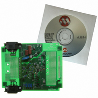
MCP3905EV
Description
BOARD DEMO FOR MCP3905
Manufacturer
Microchip Technology
Type
Other Power Managementr
Specifications of MCP3905EV
Main Purpose
Power Management, Energy/Power Meter
Embedded
No
Utilized Ic / Part
MCP3905/6
Primary Attributes
1-Phase, 120/220 VAC, On Board Transformerless AC/DC 5V Supply
Silicon Manufacturer
Microchip
Silicon Core Number
MCP3905A
Kit Application Type
Power Management
Application Sub Type
Energy Meter
Kit Contents
Board & Design Guides
Product
Power Management Modules
Lead Free Status / RoHS Status
Contains lead / RoHS non-compliant
Secondary Attributes
-
Lead Free Status / Rohs Status
Lead free / RoHS Compliant
For Use With/related Products
MCP3905
Lead Free Status / RoHS Status
Lead free / RoHS Compliant, Contains lead / RoHS non-compliant


MCP3905A/06A Evaluation Board User’s Guide
DS51567B-page 18
2.5.8
A low-cost DC power supply circuit is included on the MCP3905A/06A Evaluation
Board. This is the same DC power supply circuit used in the MCP3905A/06A Energy
Meter Reference Design. The DC power supply is created from a half-wave zener
diode-limited AC signal feeding a 7805 +5V regulator.
C
depending on the AC source expected. The board comes populated with a series
capacitor of 0.47 µF, designed to divide down an AC line voltage of 220 V
power supply is to be used with a 120 V
to 1 µF. Refer to Appendix B. “Bill Of Materials (BOM)” for detailed part information.
For more detail on this circuit design, as well as for 120V circuit specifications, refer to
AN994 “IEC Compliant Active Energy Meter Design Using The MCP3905A/06A”
(DS00994).
2.5.9
A second prototype area is included for experiments using the MCP3905A output.
All MCP3905A outputs (F
area.
2.5.10
A standard 14-pin PICtail™ daughter board connector is included on this board, as
shown in Figure 2-12. Any number of MCP3905A with PICmicro MCU meter designs
can be developed. An optical isolator is included with the MCP3905A/06A Energy
Meter Reference Design as an additional level of protection for direct-connect meters
using a shunt. It is connected to the selected output of the MCP3905A via JP5.
A pull-up resistor is required on the output of the optical isolator to allow the selected
logic signal to appear on the PICmicro MCU-based demo board, which is isolated
entirely from the MCP3905A/06A Evaluation Board. The output of the optical isolator
is connected to RC0 on this connector, as shown in Figure 2-12. RC0 was chosen to
be the default output due to the timer1 clock input on many PICmicro
FIGURE 2-12:
header. The output is connected to RC0 using a 10 k
daughter board header +5V and the PICmicro
17
To A
bias to 110 or
220V with
direct-connect
meters)
and C
GND
MCP3905A OUTPUT SELECTION
(possible
16
DC Power Supply
Output Prototype Area
Connecting the MCP3905A/06A Evaluation Board to a
PICDEM™ Demonstration Board
divide the AC signal coming directly from the line, with their values
HF
F
F
NEG
OUT1
OUT0
OUT
Optical isolation of the MCP3905A outputs to the PICkit™
JP5
OUT
OUT0
1
2
, F
U3
OUT1
3
4
, HF
RMS
10 kΩ
Pull-up
Resistor
OUT
AC source capacitor, C
, REVP) are brought out to the prototype
®
MCU header, GND.
Ω
PIC
pull-up resistor to the PICtail™
®
Daughter Board Connector
_MCU_GND
© 2009 Microchip Technology Inc.
Standard PICtail™
VCC
RC1
RC0
RC2
RC3
RC5
RC4
RA0
RA1
RA2
RA5
RA4
RA3
16
®
should change
MCUs.
RMS
11
8
9
13
14
4
5
6
7
10
1
2
3
12
. If the DC
Related parts for MCP3905EV
Image
Part Number
Description
Manufacturer
Datasheet
Request
R

Part Number:
Description:
Manufacturer:
Microchip Technology Inc.
Datasheet:
Part Number:
Description:
Manufacturer:
Microchip Technology Inc.
Datasheet:
Part Number:
Description:
Manufacturer:
Microchip Technology Inc.
Datasheet:
Part Number:
Description:
Manufacturer:
Microchip Technology Inc.
Datasheet:
Part Number:
Description:
Manufacturer:
Microchip Technology Inc.
Datasheet:
Part Number:
Description:
Manufacturer:
Microchip Technology Inc.
Datasheet:
Part Number:
Description:
Manufacturer:
Microchip Technology Inc.
Datasheet:
Part Number:
Description:
Manufacturer:
Microchip Technology Inc.
Datasheet: