DV330021 Microchip Technology, DV330021 Datasheet - Page 16
DV330021
Manufacturer Part Number
DV330021
Description
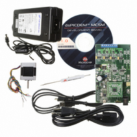
BOARD DEV DSPICDEM MCSM KIT
Manufacturer
Microchip Technology
Series
dsPIC™r
Datasheet
1.DM330022.pdf
(38 pages)
Specifications of DV330021
Main Purpose
Power Management, Motor Control
Embedded
*
Utilized Ic / Part
dsPIC33F
Primary Attributes
*
Secondary Attributes
*
Processor To Be Evaluated
dsPICDEM
Processor Series
dsPIC DSC
Interface Type
USB
Operating Supply Voltage
24 V
Silicon Manufacturer
Microchip
Silicon Core Number
DsPIC33F
Core Architecture
PIC
Core Sub-architecture
PIC33
Silicon Family Name
Piccolo
Lead Free Status / RoHS Status
Lead free / RoHS Compliant
Lead Free Status / RoHS Status
Lead free / RoHS Compliant, Lead free / RoHS Compliant
Available stocks
Company
Part Number
Manufacturer
Quantity
Price
Company:

Part Number:
DV330021
Manufacturer:
MICROCHIP
Quantity:
12 000


dsPICDEM™ MCSM Development Board User’s Guide
2.2
DS70610A-page 16
PROGRAMMING AND DEBUGGING APPLICATION CODE
4. Connect the 24V power supply to J6.
5. Press S1 to run the motor.
6. Vary the motor’s speed with the potentiometer.
7. Press S1 to switch to full-step wave mode, full-step, half-step and various
Operating the dsPICDEM MCSM Development Board using the on-board POT and
switch button cannot offer the flexibility required in most applications and it is only
intended as a quick start demonstration. To have more control over the motor using a
real-time communication tool, please refer to the next section.
The following procedure describes how to program the dsPICDEM MCSM
Development Board in Debug mode:
1. Place the dsPICDEM MCSM Development Board on a sturdy insulated platform.
2. Make sure that the dsPIC33FJ32MC204 device or an appropriate PIM is
3. Connect the stepper motor (42HS03) to J8. Connect motor phases in a bipolar
4. Connect the 24V power supply to J6.
5. Connect PICkit™ 3 In-Circuit Debugger/Programmer, MPLAB
6. Connect the USB cable to J4 and to the computer.
7. Download the code for the dsPIC33FJ32MC204 from the Microchip web site .
8. Build the project and download the program into the processor.
9. Click the Run icon when in Debug mode.
Note:
microstepping modes. Pushing S1 after the 256
the motor. Press S1 again to repeat the cycle.
mounted in the respective socket.
series connection as described in Table 2-1.
REAL ICE™ In-Circuit Emulator to the computer and to the board at J1 or J2.
For more information on running stepper motors, refer to
Section 1.4 “Reference Documents and Webinars”.
th
microstep step setting stops
© 2009 Microchip Technology Inc.
®
ICD 3 or MPLAB
Related parts for DV330021
Image
Part Number
Description
Manufacturer
Datasheet
Request
R

Part Number:
Description:
Manufacturer:
Microchip Technology Inc.
Datasheet:
Part Number:
Description:
Manufacturer:
Microchip Technology Inc.
Datasheet:
Part Number:
Description:
Manufacturer:
Microchip Technology Inc.
Datasheet:
Part Number:
Description:
Manufacturer:
Microchip Technology Inc.
Datasheet:
Part Number:
Description:
Manufacturer:
Microchip Technology Inc.
Datasheet:
Part Number:
Description:
Manufacturer:
Microchip Technology Inc.
Datasheet:
Part Number:
Description:
Manufacturer:
Microchip Technology Inc.
Datasheet:
Part Number:
Description:
Manufacturer:
Microchip Technology Inc.
Datasheet: