EVAL-ADM1176EBZ Analog Devices Inc, EVAL-ADM1176EBZ Datasheet
EVAL-ADM1176EBZ
Specifications of EVAL-ADM1176EBZ


Related parts for EVAL-ADM1176EBZ


EVAL-ADM1176EBZ Summary of contents
Page 1
... Rev. 0 Evaluation boards are only intended for device evaluation and not for production purposes. Evaluation boards are supplied “as is” and without warranties of any kind, express, implied, or statutory including, but not limited to, any implied warranty of merchantability or fitness for a particular purpose. No license is granted by implication or otherwise under any patents or other intellectual property by application or use of evaluation boards ...
Page 2
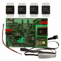
... EVAL-ADM1175/ADM1176/ADM1177/ADM1178 TABLE OF CONTENTS Product Description ......................................................................... 1 General Description ......................................................................... 1 Package Contents .............................................................................. 1 Digital Picture of the Evaluation Board ......................................... 1 Revision History ............................................................................... 2 Evaluation Board Hardware ............................................................ 3 Hardware Components ................................................................ 3 Switch Functions .......................................................................... 3 Jumper Functions ......................................................................... 4 LED Functions .............................................................................. 4 Configuration Link Functions .................................................... 4 Evaluation Board Software .............................................................. 5 Additional Features ...................................................................... 5 Powering the Evaluation Board .................................................. 5 Communicating with the Evaluation Board ............................... 5 Configuration Tool ...
Page 3
... Connects user-defined SS capacitors (C12 and C13) to the SS pin. EVAL-ADM1175/ADM1176/ADM1177/ADM1178 Device Samples Some loose samples of the device to be evaluated are included in a samples box. A single device should be placed in the socket before powering up the evaluation board. The device should be orientated in the socket such that Pin the top left corner, near C8 as shown in Figure 2 ...
Page 4
... Indicates that the FET is on and output voltage is present. D4 Alert Indicates an overcurrent alert (ADM1178 only). CONFIGURATION LINK FUNCTIONS To configure an evaluation board to a specific device, ensure that the links in Table 4 are inserted. Table 4. Link Description SL1 Configuration link applies to the ADM1175, ADM1176, and ADM1177. ...
Page 5
... ADM1177/ADM1178 device. The latest revision of this software is available to download at www.analog.com/powermonitorsw. The software is compatible with Windows® 98, 2000, and XP interface Communication between a PC and the evaluation board is achieved through the 5-pin header (J7), which should command. connected to the PC using the provided cable. CONFIGURATION TOOL ...
Page 6
... Figure 3. Evaluation Software Installation Wizard 4. Click Next to display the Destination Folder window (see Figure 4). Figure 4. Evaluation Software—Choosing a Destination Folder 5. To change the destination folder, click Browse to create a new destination folder. Otherwise, click Next. The Ready to Install the Application window appears (see Figure 5). Figure 5. Evaluation Software— ...
Page 7
... PC or click No to manually restart later. Figure 8. Installation Restart Reminder UNINSTALLING THE EVALUATION SOFTWARE Before an updated version of the evaluation software is installed, any previous version must be uninstalled. The software automatically does this once the newly downloaded file is opened. The Uninstall window appears notifying you that the previous version will be uninstalled (see Figure 9) ...
Page 8
... Figure 11. Automatically Installing Drivers for the Evaluation Board In Windows XP, a warning appears indicating that the hardware has not passed Windows logo testing to verify compatibility with Windows XP. However, the evaluation board has been tested and is compatible with Windows XP. To install the necessary drivers, click Continue Anyway (see Figure 12). ...
Page 9
... Once launched, the Evaluation Software Agreement window appears (see Figure 14). Choose I Agree to concur with the conditions, then select Continue. Figure 14. Software Agreement If the evaluation board is powered up and a ADM1175/ ADM1176/ADM1177/ADM1178 device is in the socket, the Device address search window appears. A green highlighted box corresponds to the devices I (see Figure 15) ...
Page 10
... EVAL-ADM1175/ADM1176/ADM1177/ADM1178 EVALUATION SOFTWARE—MAIN PANEL TAB The Main Panel tab of the evaluation software is shown in Figure 17. Each aspect of the main panel is discussed in detail in the following sections. Figure 17. Main Panel on User Interface COMMAND REGISTER CONTROLS Figure 18. Command Register Panel The Command Register panel allows you to control the way the device reads data ...
Page 11
... Read Status Register button in the Status Register is selected. Note that the position of Jumper LK2 for ADM1178 on the evaluation board affects the status of this flag. If the corresponding jumper is inserted in Position B, the overcurrent output flag is represented by the on-board LEDs and the indicator in the software is continuously green even when an overcurrent event occurs ...
Page 12
... ADM1175 device. Figure 29. Convert Pin Control Panel The jumper in LK3 should be in Position A to allow the evaluation software to control the convert pin. If the jumper is in Position B, the on-board switch, S6, can be used to control the conversion. The Convert Pin Control panel allows you to control the analog-to-digital conversion of voltage and/or current ...
Page 13
... Using the scale adjustment bar shown in Figure 35, you can adjust the y-axis scale of the plots to optimize them. Figure 35. Scale Adjustment Bar EVAL-ADM1175/ADM1176/ADM1177/ADM1178 On the top right corner, the Pulse button allows you to pulse the graph from real-time plotting. There is also a Scope Chart selection drop-down menu that allows you to choose from one of the three graph formats ...
Page 14
... ADM1178 devices, each device is powered using a bench supply of between 3.15 V and 16.5 V, connected to J3 (VIN) and J4 (GND). The first evaluation board should be connected to the PC using a 5-pin SMBus cable from the 5-pin header labeled J7. Each board is fitted with two MiniMolex® interconnecters, J8 and J9. ...
Page 15
... In Figure 45, the supply voltage is constant. The current associated with traces are varied. The current is varied by changing the load resistance. Turning VR1 clockwise on each respective evaluation board reduces the load resistance, hence the current increases, and vice versa. In Figure 46, the Main Panel is shown for five interconnected boards. Note that there is an extra tab entitled V, I & ...
Page 16
... EVAL-ADM1175/ADM1176/ADM1177/ADM1178 EVALUATION BOARD SCHEMATIC Figure 49. ADM1175/ADM1176/ADM1177/ADM1178 Evaluation Board Schematic Rev Page 06474-049 ...
Page 17
... SMD resistor 6 R9, R14, R15, 1 kΩ, 1%, 0805 SMD resistor R16, R17, R18 1 R10 100 Ω, 1%, 0805 SMD resistor 1 R11 2.2 kΩ, 1%, 0805 SMD resistor EVAL-ADM1175/ADM1176/ADM1177/ADM1178 Manufacturer Manufacturer Number Phycomp 2238 580 15632 Phycomp 2238 580 15645 Multicomp B0805R474KCT Multicomp ...
Page 18
... MSO10, SMD, ADM1175-2ARMZ/ADM1176- 2ARMZ/ADM1177-2ARMZ/ADM1178-2ARMZ 1 VR1 Trimmer potentiometer, VRES ROTARY 2K 1 FEC = Farnell Electronics. ORDERING GUIDE Model Description EVAL-ADM1175EBZ 1 Evaluation Board 1 EVAL-ADM1176EBZ Evaluation Board EVAL-ADM1177EBZ 1 Evaluation Board 1 EVAL-ADM1178EBZ Evaluation Board 1 CABLE-SMBUS-5PINZ 5-Pin SMBus Cable (Parallel Port) 1 USB-5PSMBUS-CABLEZ 5-Pin SMBus Cable (USB Port RoHS Compliant Part ...
Page 19
... NOTES EVAL-ADM1175/ADM1176/ADM1177/ADM1178 Rev Page ...
Page 20
... EVAL-ADM1175/ADM1176/ADM1177/ADM1178 NOTES ©2008 Analog Devices, Inc. All rights reserved. Trademarks and registered trademarks are the property of their respective owners. EB06474-0-5/08(0) Rev Page ...