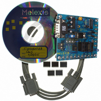
EVB90308 Melexis Inc, EVB90308 Datasheet

EVB90308
Specifications of EVB90308
DK90308
Related parts for EVB90308
EVB90308 Summary of contents
Page 1
MLX90308D & MLX90314B The MLX90308D and MLX90314B sensor interfaces provide a versatile programmable interface to a wide assortment of sensors and transducers. The sensor interface provides gain and offset control, linearization and temperature correction for sensor. The device contains on ...
Page 2
Main Dialog Box Upon starting the software the dialog box below, figure 1, will appear. Status Display Window Figure 1, Main dialog box. Software Title The applicable part number for which the software is intended to work with is ...
Page 3
Figure 2, Software revision dialog box. Connect The ‘Connect’ button will bring up the ‘Find Controller’ dialog box. This is needed to establish communications between the PC and the sensor interface. A description of this dialog box is in section ...
Page 4
Download ASIC This button downloads all of the data from the sensor interface to the PC. This data is from both RAM and EEPROM. The data must be downloaded from the sensor interface before it can be edited using the ...
Page 5
Save to File This button is used to save the RAM and EEPROM data to a file. The data can be used as a starting point for calibrating another sensor-sensor interface. A standard dialog box is called to allow the ...
Page 6
Serial Port The serial port pull down menu allows the user to select the serial port the sensor interface is connected to. The options are Com1 and 4. The software assumes standard port addresses and IRQs are defined ...
Page 7
Current Mode This box enables Current Mode output of the sensor interface. Voltage mode can be used simultaneously with Voltage Mode. Either Voltage Mode and/or Current Mode should always be enabled. Turbo This box enables the Turbo mode of the ...
Page 8
Analog Mode This box enables the chip to operate with a completely analog signal path from sensor input to signal output. This provides the best accuracy however signal linearization is not available in Analog Mode. Analog Mode is mutually exclusive ...
Page 9
Checksum Test This box enables the Checksum Test to ensure the integrity of the contents of the EEPROM. When enabled the checksum is calculated during a reset, either power- soft reset. The sum of all of the EEPROM ...
Page 10
The invert signal control swaps the VBN and VBP signals at the front end of the signal path. This has the same effect as rewiring the connections from the sensor. Temp Amp Gain The temperature amplifier gain control (GNTP) is ...
Page 11
Checksum The Checksum data box is for display only. The software calculates the checksum whenever an upload to EEPROM is performed. This happens whether the Checksum test is enabled or not. This field is read only. Checksum Error This data ...
Page 12
Alarm Function OUTPUT MLX90308 High Output Low Output Low High Trigger Trigger Input Signal Figure 7, Alarm Function High Trigger This value is the source signal threshold above which the high output value will be sent to output. This is ...
Page 13
Level Steering The Level Steering function provides two digital outputs acting as a two bit analog to digital converter, see figure 8. The converted analog signal is selected by the user as well as the points at which the two ...
Page 14
Source The source signal for Alarm Mode can be chosen from 4 points which the microcontroller has access to. These are four internal points input amplifier out (IAO), gain amplifier out (GNO), temperature amplifier out (TPO), and voltage mode output ...
Page 15
Temperature Compensation OF & GN MLX90308 OFTC3 OFTC2 GNTC3 OFTC1 GNTC2 GNTC1 Application's temperature range Temperature Figure 9, Temperature Compensation The first temperature gap is slightly different than the other three. The compensation is ...
Page 16
GNTC The GNTC values are the gain temperature compensation values for each of the four temperature gaps, GNCT1, GNTC2, GNTC3, and GNTC4. These values are used to adjust the signal up or down based on the relative temperature within a ...
Page 17
OFTC The OFTC values are the offset temperature compensation values for each of the four temperature gaps, OFCT1, OFTC2, OFTC3, and OFTC4. These values are used to adjust the signal’s offset up or down based on the relative temperature within ...
Page 18
Signal Linearity Correction Output MLX90308 PC5 PC4 PC3 PC2 PC1 Input Signal (units) Figure 11, Signal linearization The signal linearization is an adjustment to the output level based on the input signal level. Adjustment ...
Page 19
Programming 4.1) Baseline Calibration The baseline calibration involves setting the operating modes and temperature gain along with the coarse and fixed gain and offset. Setting the operating modes Voltage and/or Current mode, turbo mode, Analog or Digital mode, Level ...
Page 20
The compensation coefficients for the first gap (OFTC1 and GNTC1) apply to digitized filtered temperature values from T1 down to zero. The fourth gap coefficients ...
Page 21
For less than four temperature gaps the last temperature point should be set to 1023. This means that the last gap extends out to the end of the temperature range. 4.4) Signal linearization The signal linearization is only available when ...


