IS-DEM KIT-2 NKK Switches, IS-DEM KIT-2 Datasheet
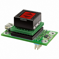
IS-DEM KIT-2
Specifications of IS-DEM KIT-2


Related parts for IS-DEM KIT-2


IS-DEM KIT-2 Summary of contents
Page 1
E. Gelding Drive Scottsdale, AZ 85260 USA 1-877-2BUYNKK (228-9655) Phone 480.991.0942 Fax 480.998.1435 www.nkksmartswitch.com 06–07 Demonstration Kit User Guide ...
Page 2
... Easy Editor,” downloaded to the kit via USB Type A-mini B cable (re- quired for connection to a PC). “IS Easy Editor” is the software to create and edit graphics. A variety of tool functions allows you to customize bitmap images as well as change the setting of the backlight. ...
Page 3
... Do not exceed 60°C at the LCD level the LCD is accidentally broken, avoid contact with the liquid and wash off any liquid spills to the skin or clothing not connect to PC via USB when IS Easy Disply Kit is mounted on battery box. 6. Deviation of drive current and temperature may change LCD contrast. ...
Page 4
... HARDWARE INSTALLATION The Connector Block (A) is required to illuminate the backlight of the DEM KIT while programming through the USB Type A-mini B cable. Pin 1 Connector Block (A) 4 (OPTIONAL) BATTERY BOX SPECIFICATIONS The Battery Box provides portability to demonstrate functionality without any system connections. • Power Switch activates power Connect as • ...
Page 5
... Read installation manual on CD (See Figure A not connect hardware (IS Easy Display Controller) until installation of drivers. 3. Turn off all resident software (i.e., antivirus software) before beginning installation. 4. Make sure you have administrative rights to install software on your computer. 5. Minimum system requirements: • CPU Pentium or compatible processor • OS ...
Page 6
... Select “IS Easy Editor” and click “Change/Remove”. 6 CONTROLLING INFORMATION (CONTINUED) Control of Backlight LEDs For LED control, settings of “IS Easy Editor” are transferred to IS Display Controller via switching transistors connected to LED_1c/LED_2c. Figure B NOTE: Consult factory if using IS Switch or Display other than what is • ...
Page 7
... CONTROLLING INFORMATION Control of Data Bitmap data is transferred to IS Easy Display Controller by setting the 6-bits parallel TTL level signals (terminals 11~16). To display desired bitmaps in “IS Easy Editor”, refer to diagram below and set appropriate values to terminals. Connector CN2 Terminal Number/Logic Level Bitmap ...
Page 8
... LED common Common anode of backlight LEDs of IS (anode) External power supply terminal for drive of LEDs Ground GND terminal Switch 1 IS15: Connected to switch terminal 1; IS01: no connection Switch 2 IS15: Connected to switch terminal 2; IS01: no connection 7 LED_1k LED 1 (cathode) Cathode terminal of backlight LED 1 8 LED_2k ...