EK15 Cirrus Logic Inc, EK15 Datasheet - Page 2
EK15
Manufacturer Part Number
EK15
Description
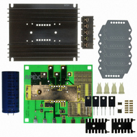
EVALUATION KIT FOR SA08
Manufacturer
Cirrus Logic Inc
Series
Apex Precision Power™r
Datasheet
1.EK15.pdf
(4 pages)
Specifications of EK15
Main Purpose
Power Management, H Bridge Driver (Internal FET)
Embedded
No
Utilized Ic / Part
SA08
Primary Attributes
16 V ~ 450 V Supply, 20A Output
Secondary Attributes
Assembly Required
Product
Amplifier Modules
Description/function
Audio Amplifiers
Lead Free Status / RoHS Status
Contains lead / RoHS non-compliant
Other names
598-1460
EK15
EK15


EK15
ASSEMBLY
During assembly refer to Figure 1 and
2
1. From the DUT of the PCB insert and
2. Solder the 3 surface mount ceramic
3. From the component side of the PCB
4. Two values of current limiting power
5. Insert the electrolytic capacitor into
6. From the circuit side, push spacer
7. Apply TW05 thermal washer to the
8. Use #14 sleeving to insulate and align
9. Mount amplifier to heatsink using #6
10. Install components as needed. Ex-
11. Insert amplifier pins into cage jacks
Figure 2.
solder the 12 cage jacks. Also solder
the cage jacks from the circuit side
as well, making sure the cage jack
remains flush with the component side
of the PCB.
capacitors to the component side of
the PCB.
insert the terminal strip. Solder from
the circuit side of the PCB. Be sure that
the GND terminal hole in the PCB is
fully filled with solder.
resistors are supplied. Select one
value (see the amplifier data sheet to
learn how to calculate which resistor
will suit your need). Coat the backside
of the power resistor with heat sink
compound (not supplied). Using 4-40
screws and nuts (not supplied) mount
the resistors to the two small heat sinks
supplied. Solder the resistor/heat sink
assembly to the component side of the
PCB.
the PCB from the component side and
solder from the circuit side making sure
to fill the mounting holes with solder.
grommets into PCB until fully seated.
Grommets will snug when screws are
inserted for heatsink mounting.
bottom of the amplifier.
at least 2 opposite pins of the amplifier.
screws and nuts. Torque the part to
the specified 8 to 10 in-lbs (.9 to 1.13
N*M). Do not over torque.
ternal connections may be soldered
directly or standard banana jacks may
be soldered to the large pads at the
edge of the PCB.
and fasten PCB to heatsink.
BOTTOM SIDE
TOP SIDE
M I
R1
EVAL19 R-C
COMPONENT SIDE
C
R
O
SHDN
T
E C H
N
O
D1
TB1
L
P r o d u c t I n n o v a t i o n F r o m
R3
O
RAMP/-PWM
FLAG
G
+
OR
Y
FIGURE 2. PCB
+
PWR
GND
SIG
GND
Rb
CVs3
C3
B OUT
C2
GND
SIG
6
7
6
+Vs
5.500
C1
+PWM
A OUT
J1
12
1
R4
1
Vcc
Ra
SPARE
R2
IC
Vcc
SPARE
IC
SIG
GND
EK15U
4.686
Related parts for EK15
Image
Part Number
Description
Manufacturer
Datasheet
Request
R

Part Number:
Description:
Development Kit
Manufacturer:
Cirrus Logic Inc
Datasheet:
Part Number:
Description:
Development Kit
Manufacturer:
Cirrus Logic Inc
Datasheet:


Part Number:
Description:
High-efficiency PFC + Fluorescent Lamp Driver Reference Design
Manufacturer:
Cirrus Logic Inc
Datasheet:
Part Number:
Description:
Development Kit
Manufacturer:
Cirrus Logic Inc
Datasheet:
Part Number:
Description:
Development Kit
Manufacturer:
Cirrus Logic Inc
Datasheet:

Part Number:
Description:
Development Kit
Manufacturer:
Cirrus Logic Inc
Datasheet:
Part Number:
Description:
Development Kit
Manufacturer:
Cirrus Logic Inc
Datasheet:
Part Number:
Description:
Development Kit
Manufacturer:
Cirrus Logic Inc
Datasheet:
Part Number:
Description:
Development Kit
Manufacturer:
Cirrus Logic Inc
Datasheet:

Part Number:
Description:
EVALUATION BOARD FOR CS8427
Manufacturer:
Cirrus Logic Inc
Datasheet:

Part Number:
Description:
BOARD EVAL FOR CS8416 RCVR
Manufacturer:
Cirrus Logic Inc
Datasheet:

Part Number:
Description:
EVALUATION BOARD FOR CS8420
Manufacturer:
Cirrus Logic Inc
Datasheet:

Part Number:
Description:
KIT DEVELOPMENT EP9315 ARM9
Manufacturer:
Cirrus Logic Inc
Datasheet:

Part Number:
Description:
KIT DEVELOPMENT EP9302 ARM9
Manufacturer:
Cirrus Logic Inc
Datasheet: