DB62 Cirrus Logic Inc, DB62 Datasheet - Page 4
DB62
Manufacturer Part Number
DB62
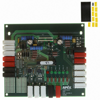
Description
DEMO BOARD FOR SA305EX
Manufacturer
Cirrus Logic Inc
Series
Apex Precision Power™r
Datasheet
1.DB62.pdf
(6 pages)
Specifications of DB62
Main Purpose
Power Management, Motor Control
Embedded
No
Utilized Ic / Part
SA305EX
Primary Attributes
3-Ph Brushless DC (BLDC) Motors
Secondary Attributes
PWM Inputs
Processor To Be Evaluated
PIC18F2331
Lead Free Status / RoHS Status
Contains lead / RoHS non-compliant
Lead Free Status / RoHS Status
Lead free / RoHS Compliant, Contains lead / RoHS non-compliant
Other names
598-1394


DB62
ASSEMBLY
siderations section to be able to differentiate between required
and recommended components. The assembly instructions
below cover all the components in the board irrespective of
whether they are required or optional. Use the bread board-
ing area for any additional circuitry (example: pull-up for hall
sensors) that might be required.
1. Note that each side of the circuit board is identified as either
2. From the component side, solder a jumper between SGND
3. From the component side, solder the surface mount capaci-
4. From the component side, solder jumpers into place for
5. From the component side, solder pin sockets into place
6. Study the DIP28 socket and notice the notch on one end.
7. Solder one end of an insulated jumper wire to Pin 11 of the
8. From the component side, insert the potentiometers VDUC
9. From the component side, insert switches SW1 and SW2
10. From the component side, insert White Test Points into
11. From the component side, insert the following components:
12. From the component side, insert LED’s D7, D9, D12, D11,
13. If Hall Effect Sensor pull-up resistors are necessary, install
14. Install pin socket in bread board directly under DGND pin
15. From the component side, insert the 4MM PCB sockets.
APEX MICROTECHNOLOGY CORPORATION • 5980 NORTH SHANNON ROAD • TUCSON, ARIZONA 85741 • USA • APPLICATIONS HOTLINE: 1 (800) 546-2739
4
Before starting the assembly, please review the special con-
the “component side” or “bottom side.” The component side
is labeled on the silk screen side of the board. Cut the MS11
strip into strips of 12 and 11. Discard the remaining small
strip of 7. Insert the two strips into the two rows of holes
for the DUT from the component side of the PCB. From
the bottom side, solder all cage jacks to the circuit board
pads. Be sure that the cage jacks are fully seated before
soldering. Be careful that the solder does not flow into the
cage jack. Remove the plastic carrier strips.
and DGND and another between PGND and DGND.
tors, C1, C4, C7 and C11 and resistors R5 and R10.
the following components: R12, R14, R15, R27, R28 and
R29.
for the following components: C5, C8, C10, R8, J1A (2 pin
sockets), J1B, J2A, J2B, J3A, J3B and DGND.
From the component side, insert the socket, making sure
that the socket has the same orientation as the silk screen
diagram. Solder in the socket from the bottom side.
DIP28 socket, and plug the other end into one of the two
pin sockets at J1A.
and VFREQ in the specified orientation and solder from the
bottom side. Carefully bend the potentiometers down to a
horizontal position.
and solder from the bottom side.
TP1, TP2, PWM_HC1, PWM_HB1 and PWM_HA1.
Insert Black Test Points into PWM_LC1, PWM_LB1 and
PWM_LA1. Solder all test points from the bottom side.
R1, R2, R3, R6, R7, R11, R17, R20, R26, R22, R21, R18,
R23, R24 and R25, and solder from the bottom side.
D10 and D8 and solder from the bottom side.
resistors in bread board to the left of the HALL_A, HALL_B
and HALL_C sockets.
socket.
Note that there are 4 Black sockets, for SGND, DGND,
16. From the component side, insert Schottky diodes D1, D2,
17. If Hall Sensor pull-up resistors are to be used, at this time,
18. On the bottom side, connect a wire from OFF PCB connec-
19. On the bottom side, connect 16-gauge wire from D4 cath-
20. From the component side, insert the snubber resistors,
21. From the component side, insert the electrolytic capacitors,
22. Install jumper as desired for J3A and/or J3B. Install jumper
23. Using appropriate hardware, install stand-offs at each
24. Clip the SA305 into the HS32 heat sink with the CLAMP05
SOFT-START FEATURE:
duty cycle at start-up is low and the motor ramps up to the
specified speed reference. The startup duty cycle should be
programmed so that the over current limit of the SA305 is not
exceeded at start-up. The algorithm enables controlling the
rate of acceleration and consequently the maximum current.
When the motor is to be reversed the soft-start algorithm is
once again initiated, causing the motor to gradually accelerate
in the opposite direction. Please refer to application note 45
for details on the soft-start algorithm.
FAULT RESET:
pin to resume normal operation when the part is in a latched
fault condition because of Short-circuit, Over Temperature
(>160°C) or Over-Current (>10 A). In the DB62 board, there
is a provision to reset the part automatically without human
intervention. A jumper needs to be connected between J1A
and P11 of MCU as shown in the schematic. When a fault
occurs, an interrupt is generated which in turn starts generat-
ing pulses at P11 to reset the SA305.
A soft start algorithm has been developed so that the
The SA305 requires an external reset pulse at the disable
PGND and OFF. There are 5 Red sockets, for VPWR,
VDD2, VDD, FAULT and WARNING. The remaining 10
White sockets are for the remaining Input/Output signals.
Solder all sockets from the bottom side.
D3, D4, D5 and D6. Solder from the bottom side. Do NOT
trim off excess lead length at this time.
on the bottom side, connect wires from HALL_A, HALL_B,
HALL_C and VDD to the appropriate bread-board sockets
as determined in Step 13.
tor to pin socket directly under DGND pin socket (installed
in Step 14).
ode to AOUT PCB connector. Connect another 16-gauge
wire from D6 cathode to COUT PCB connector. Connect
a third 16-gauge wire from D5 cathode to BOUT PCB
connector. Now, trim off the excess lead length from the
Schottky diodes.
R13, R16 and R19, and solder from the bottom side. Insert
snubber capacitors, C5, C8 and C10 into the previously
installed pin sockets.
C12 and C2, and solder from the bottom side.
from J1A to J1B. If desired, jumper J2A and J2B.
corner hole.
clip. Carefully insert the part with the heat sink into the
MS11 sockets. Bolt the heat sink in from the bottom side
of the board using the holes provided on the PCB.
EVALUATION KIT FOR
SA305EX
Related parts for DB62
Image
Part Number
Description
Manufacturer
Datasheet
Request
R

Part Number:
Description:
Development Kit
Manufacturer:
Cirrus Logic Inc
Datasheet:
Part Number:
Description:
Development Kit
Manufacturer:
Cirrus Logic Inc
Datasheet:


Part Number:
Description:
High-efficiency PFC + Fluorescent Lamp Driver Reference Design
Manufacturer:
Cirrus Logic Inc
Datasheet:
Part Number:
Description:
Development Kit
Manufacturer:
Cirrus Logic Inc
Datasheet:
Part Number:
Description:
Development Kit
Manufacturer:
Cirrus Logic Inc
Datasheet:

Part Number:
Description:
Development Kit
Manufacturer:
Cirrus Logic Inc
Datasheet:
Part Number:
Description:
Development Kit
Manufacturer:
Cirrus Logic Inc
Datasheet:
Part Number:
Description:
Development Kit
Manufacturer:
Cirrus Logic Inc
Datasheet:
Part Number:
Description:
Development Kit
Manufacturer:
Cirrus Logic Inc
Datasheet:

Part Number:
Description:
EVALUATION BOARD FOR CS8427
Manufacturer:
Cirrus Logic Inc
Datasheet:

Part Number:
Description:
BOARD EVAL FOR CS8416 RCVR
Manufacturer:
Cirrus Logic Inc
Datasheet:

Part Number:
Description:
EVALUATION BOARD FOR CS8420
Manufacturer:
Cirrus Logic Inc
Datasheet:

Part Number:
Description:
KIT DEVELOPMENT EP9315 ARM9
Manufacturer:
Cirrus Logic Inc
Datasheet:

Part Number:
Description:
KIT DEVELOPMENT EP9302 ARM9
Manufacturer:
Cirrus Logic Inc
Datasheet: