EVL6563S-400W STMicroelectronics, EVL6563S-400W Datasheet - Page 31
EVL6563S-400W
Manufacturer Part Number
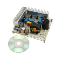
EVL6563S-400W
Description
EVAL BOARD FOR L6563(400W)
Manufacturer
STMicroelectronics
Type
Motor / Motion Controllers & Driversr
Specifications of EVL6563S-400W
Main Purpose
Power Management, Power Factor Correction
Embedded
No
Utilized Ic / Part
L6563
Primary Attributes
400W Power Factor Correction and Preregulator Combination
Secondary Attributes
Transition Mode & Active Tracking Boost Function.
Maximum Operating Temperature
+ 60 C
Product
Power Management Development Tools
Lead Free Status / RoHS Status
Lead free / RoHS Compliant
For Use With/related Products
L6563S
Other names
497-10488
Available stocks
Company
Part Number
Manufacturer
Quantity
Price


L6563S
Figure 42. Effect of boost inductor saturation on the MOSFET current and detection method
6.7
occasionally slightly saturate when the PFC stage is restarted because of a larger load
demand. This happens when the restart occurs at an unfavorable line voltage phase, i.e.
when the output voltage is significantly below the rectified peak voltage. As a result, in the
boost inductor the inrush current coming from the bridge rectifier adds up to the switched
current and, furthermore, there is little or no voltage available for demagnetization.
To cope with a saturated inductor, the L6563S is provided with a second comparator on the
current sense pin (CS, pin 4) that stops the IC if the voltage, normally limited within 1.1 V,
exceeds 1.7 V. After that, the IC will be attempted to restart by the internal starter circuitry;
the starter repetition time is twice the nominal value to guarantee lower stress for the
inductor and boost diode. Hence, the system safety will be considerably increased.
Power management/housekeeping functions
A special feature of this IC is that it facilitates the implementation of the “housekeeping”
circuitry needed to co-ordinate the operation of the PFC stage to that of the cascaded DC-
DC converter. The functions realized by the housekeeping circuitry ensure that transient
conditions like power-up or power down sequencing or failures of either power stage be
properly handled.
This device provides some pins to do that. One communication line between the IC and the
PWM controller of the cascaded dc-dc converter is the pin PWM_LATCH (
which is normally open (high impedance) when the PFC works properly, and goes high if it
loses control of the output voltage (because of a feedback loop disconnection) with the aim
of latching off the PWM controller of the cascaded dc-dc converter as well (see “Feedback
failure protection” section for more details).
A second communication line can be established via the disable function included in the
PFC_OK pin (see “Feedback failure protection” section for more details). Typically this line is
used to allow the PWM controller of the cascaded dc-dc converter to drive in burst mode
operation the L6563S in case of light load and to minimize the no-load input consumption.
Interface circuits like those are shown in
Doc ID 16116 Rev 4
Figure 43
.
Application information
Figure 44
b),
31/43
Related parts for EVL6563S-400W
Image
Part Number
Description
Manufacturer
Datasheet
Request
R

Part Number:
Description:
EVAL BOARD FOR L6563(100W)
Manufacturer:
STMicroelectronics
Datasheet:

Part Number:
Description:
EVAL BOARD FOR L6563(250W)
Manufacturer:
STMicroelectronics
Datasheet:

Part Number:
Description:
Power Management Modules & Development Tools Tranisition Mode PFC L6563S EVL Board
Manufacturer:
STMicroelectronics
Datasheet:

Part Number:
Description:
EVAL BOARD L6563 (200W)
Manufacturer:
STMicroelectronics
Datasheet:
Part Number:
Description:
STMicroelectronics [RIPPLE-CARRY BINARY COUNTER/DIVIDERS]
Manufacturer:
STMicroelectronics
Datasheet:
Part Number:
Description:
STMicroelectronics [LIQUID-CRYSTAL DISPLAY DRIVERS]
Manufacturer:
STMicroelectronics
Datasheet:

Part Number:
Description:
BOARD EVAL FOR MEMS SENSORS
Manufacturer:
STMicroelectronics
Datasheet:
Part Number:
Description:
NPN TRANSISTOR POWER MODULE
Manufacturer:
STMicroelectronics
Datasheet:
Part Number:
Description:
TURBOSWITCH ULTRA-FAST HIGH VOLTAGE DIODE
Manufacturer:
STMicroelectronics
Datasheet:
Part Number:
Description:
Manufacturer:
STMicroelectronics
Datasheet:
Part Number:
Description:
DIODE / SCR MODULE
Manufacturer:
STMicroelectronics
Datasheet:
Part Number:
Description:
DIODE / SCR MODULE
Manufacturer:
STMicroelectronics
Datasheet: