ISD-ES15100_USB Nuvoton Technology Corporation of America, ISD-ES15100_USB Datasheet
ISD-ES15100_USB
Specifications of ISD-ES15100_USB


Related parts for ISD-ES15100_USB

ISD-ES15100_USB Summary of contents
Page 1
... ISD-VPE15100 User’s Manual ISD15100 Series Multi-Message Record/Playback Devices with Digital Audio Interface PRELIMINARY Publication Release Date: May 21, 2008 Revision 151.003 ...
Page 2
... Configuration ............................................................................................. 15 2.7 Memory Map ............................................................................................. 16 2.8 Archive and Clean ..................................................................................... 17 3. Evaluation System.............................................................................................19 3.1 EV Board Overview ................................................................................... 19 3.1.1 Hook the EV Board .............................................................. 21 3.2 Programming the ISD151xx ...................................................................... 21 4. USB Emulation ..................................................................................................23 4.1 Audio Cmds............................................................................................... 23 4.2 Digital Cmds .............................................................................................. 25 4.3 Enriched Commands & USB Logs ............................................................ 27 5. Revision History ................................................................................................28 PRELIMINARY Publication Release Date: May 21, 2008 Revision 151 ...
Page 3
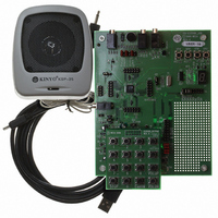
... Your evaluation kit should contain the following: • One CD for ISD15100 GUI Software set-up program and documentations User login ID and Password (without it you cannot install the software) o • ISD15100 evaluation board (ISD-ES15100_USB). With an 8-ohm speaker and a mini-USB cable. o Equipment requirements: ⇒ PC running Windows XP, NT, or 2000 1.1 Standalone Operations The EV board can be operated standalone or controlled by VPE ...
Page 4
... After VPE is properly installed, plug in the EV board to PC; then users shall see a message popped up as Figure 1-1; select ‘install from a list or specific location (Advanced)’, and then click on ‘Next’. USB driver is located in the VPE installation folder, which by default is "c:\Program Files\ISD- VPE15100\EmDriver\" as Figure 1-2; Click on ‘OK’. ...
Page 5
... You will see a query as below. Click on Yes to save project. o • Whenever the EV board is connected to PC, the button “Burn Device” is effective. Click that VPE will first chip-erases the ISD15100 and then downloads the programming file. • ‘Audio Cmds’ screen and try those voice prompts and voice macros. PRELIMINARY Publication Release Date: May 21, 2008 Revision 151 ...
Page 6
... Build the Example Project An example project named ISD15100example is pre-programmed into the EV board; the example project can be found in the CD. This project does the following: • When powered on (power supplied or a high pulse on RESET pin): Set clock source to 4MHz crystal, o Set playback path to PWM, ...
Page 7
... Please note that the clock setting (B) here is ONLY for VP compression for making a project. Users also need to set the clock for the ISD chip by either setting it in their POI/PU macros or by sending SPI commands after the chip powers up. The default clock setting for ISD chip when POI/PU: • ...
Page 8
Advanced Clock Configuration The Clock Source (A) includes four clock sources: • Internal oscillator, • Internal oscillator with external resistor, • I2S clock, and • Crystal. The selected clock will feed to the phase-lock-loop ...
Page 9
If users need really high quality, they might want to try 44.1 kHz sampling rate. According to Table 2-2, users can use an 11.2896 MHz crystal and set the PLL ...
Page 10
... SPI_SND_DEC. The added voice prompts will appear on the ‘Voice Macro’ screen for voice macro script programming. 2.4 Reserved Memory Recording Memory Pointer (RMP) divides the ISD15100 memory space into two blocks: • Reserved Memory, • Recording Memory. RMP is a two-byte address pointer pointing to a 4kbyte memory sector which is the first sector available for message recordings ...
Page 11
... Figure 2-7 Example of ISD15100 Memory Map On the ‘Reserved Memory’ screen, users reserve memory sectors for message recordings: • Empty messages (A): An Empty Message is an empty 4kByte memory sector reserved for message o recordings. An SPI record command pointing to the Empty Message starts the message recording and will continue to record to the free memory sectors located in Recording Memory if the message recording is over 4kByte ...
Page 12
... Wait until current play command finishes before executing next macro instruction. o The ISD15100 has a built-in command buffer so that consecutive commands can be executed one after another seamlessly. However, some commands won’t go through command buffer; therefore, they won’t wait. Users may refer to the design guide; section 13 SPI Commands, Table 13-2, for details ...
Page 13
Commands for adjusting volume won’t go through the command buffer; therefore, they will be executed immediately. Below is an example where the volume is immediately decreased when VP_A starts to play. • Play VP_A ...
Page 14
Figure 2-9 Voice Macro Editor Publication Release Date: May 21, 2008 PRELIMINARY 14 Revision 151.003 ...
Page 15
... Figure 2-10 Set a Playback Path to PWM 2.6 Configuration The Configuration screen aims to ease the task of configuring the ISD15100. To set the configuration registers, microcontroller could either send several ‘write config register’ commands or simply issue a Voice Macro command which consists of a group of ‘write config register’ commands. ...
Page 16
... Memory Map Memory Map is the last step to generate the programming file to be burned into the ISD15100 memory. The programming file is a binary file with mem extension. In this screen users will see how each VP, VM, and message is assigned an address and/or an index. To activate the process, click on ‘ ...
Page 17
... For example, if you create an ISD15100 project in a network share folder which is, say, mapped to T drive, you cannot just send this project to other people because “T” drive means nothing to other people ...
Page 18
The Clean function deletes the contents in the BinFile and WavFile directories as they can be regenerated. The WavFile directory contains wave files of re-sampled and de-compressed voice prompts. The BinFile directory contains files of compressed voice prompts. When a ...
Page 19
... EV Board Overview Figure 3-2 below is the ISD15100 EV board. On the right hand side is the ISD15U110 (A), our ISD USB1.1 controller especially designed for ChipCorder ISD15100 family. In the middle is the ISD15108 (B), 8-minute duration based on 8 kHz & 4-bit ADPCM. On the left hand side are analog circuitry and connectors for recording and playback. Upper left corner is a 7-segment display (C) controlled by four GPIO pins of ISD15108 (B). Upper right corner is a hole-array (D) for users’ ...
Page 20
... Use an I/O pin to “physically” enable/disable the microphone as the EV board does. • AUXIN (N): Voltage-type single-ended input. PWM ( direct speaker drive. In ISD15100, it can also be configured as: • Voltage-type differential output (BTL). BTL can directly drive the speaker, but then the volume level won’ loud as o PWM ...
Page 21
... Hi-Lo Systems All-100 Gang-Programmer: 4-socket gang-programmer http://www.hilosystems.com.tw/. o • Prospect IT2000: 8-socket gang-programmer (under development) http://www.prospect.com.tw/. o Figure 3-2 ISD-ES15100_USB Function Table 3-1 EV Board Configuration V Board 5100, they may want to use their EV board by USB; however, whenever VPE is launch, by unched, ISD15U ...
Page 22
... Figure 3-3 ISD-ES15100_PROG Publication Release Date: May 21, 2008 PRELIMINARY 22 Revision 151.003 ...
Page 23
... To erase a message, simply specify the address and then click on ‘Erase Msg At’ (E). Addresses of recorded messages are shown on the Message List. (F) ‘Get Msg List’ (G) is not an ISD15100 command indeed a bunch of digital-read commands used to scan the memory for messages. The first byte of each memory sector shows whether or not a beginning of message is inside the memory sector. VM (H) & ...
Page 24
... Figure 4-1 SPI Send Compressed Data to Decode Users can try different clock settings (S). Please note that clock setting must match the real configuration on board or the ISD15100 won’t work. Below is a table of some common settings: 0x34 Internal oscillator with internal resistor ...
Page 25
... Status’ and ‘Read INT’ (U) both read back the two-byte ISD15100 status. The only difference is that ‘Read INT’ clears the pending interrupt signal as well. ISD15100 will not generate a new interrupt signal if there is a pending one. ‘Saved Configurations’ ( copy from the ‘Configuration’ screen. Double-click on a setting to write to the ISD15100 ...
Page 26
... To update the memory contents from the screen: • Read out the ISD15100 data and have it displayed on screen as described above. • Edit the data contents on screen. The first sector (sector 0) is about the ISD15100 configuration. Do not mess it up. o • Specify to update the memory contents from screen (L). • ...
Page 27
... Compare to another log example of executing VM 2 with enriched off and auto-status-checking disabled: /---------------------------------------------- Execute VM: ExeVM: 0xB0 0x00 0x02 \---------------------------------------------- Since the enriched is off, VPE does not check the ISD15100 status or signal path before issuing the command. Figure 4-3 Digital Cmds CFG Readback: 0x44 Publication Release Date: May 21, 2008 PRELIMINARY 27 ...
Page 28
Revision History Version Date 151.003 May 21, 2008 PRELIMINARY Description Initial release: Publication Release Date: May 21, 2008 28 Revision 151.003 ...