CP2103EK Silicon Laboratories Inc, CP2103EK Datasheet - Page 4
CP2103EK
Manufacturer Part Number
CP2103EK
Description
KIT EVAL FOR CP2103 USB TO UART
Manufacturer
Silicon Laboratories Inc
Specifications of CP2103EK
Main Purpose
Interface, USB 2.0 to UART (RS232) Bridge
Embedded
No
Utilized Ic / Part
CP2103
Primary Attributes
Full Speed, 300 bps to 1 Mbps
Secondary Attributes
Software, Connector Provides Direct Access to UART Signals
Processor To Be Evaluated
CP2103
Interface Type
RS-232, USB
Silicon Manufacturer
Silicon Labs
Silicon Core Number
CP2103
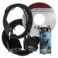
Kit Contents
Evaluation Board, RS-232 Cable, USB Cable And Driver CD
Development Tool Type
Hardware / Software - Eval/Demo Board
Lead Free Status / RoHS Status
Contains lead / RoHS non-compliant
Lead Free Status / RoHS Status
Lead free / RoHS Compliant, Contains lead / RoHS non-compliant
Other names
336-1163
Available stocks
Company
Part Number
Manufacturer
Quantity
Price
Company:

Part Number:
CP2103EK
Manufacturer:
Silicon Labs
Quantity:
135


CP2103-EK
5. Target Board
The CP2103 Evaluation Kit includes an evaluation board with a CP2103 device pre-installed for evaluation and pre-
liminary software development. Numerous input/output (I/O) connections are provided to facilitate prototyping using
the evaluation board. Refer to Figure 3 for the locations of the various I/O connectors.
5.1. LED Headers (J5, J6)
Connectors J5 and J6 are provided to allow access to the GPIO pins on the CP2103. Place shorting blocks on J5
and J6 to connect the GPIO pins to the four green LEDs D0 - D3. These LEDs can be used to indicate active
communications through the CP2103. Table 1 shows the LED corresponding to each header position.
5.2. Universal Serial Bus (USB) Interface (J3)
A Universal Serial Bus (USB) connector (J3) is provided to facilitate connections to the USB interface on the
CP2103. See Table 2 for the USB pin definitions.
4
J1
J2
J3
J4, J7
J5, J6
D0–D3
D4
DB9 connector for RS232 interface
UART signal access connector
USB connector for USB interface
Power Connector
GPIO Access Connector
Green GPIO LEDs
Red SUSPEND indicator LED
Table 2. USB Connector Pin Descriptions
J1
Figure 3. CP2103 Evaluation Board
Transceiver
Pin #
Table 1. J5 and J6 LED Locations
LED
D0
D1
D2
D3
RS232
1
2
3
4
J4
Pin 2
_________
SUSPEND
J2
Rev. 0.3
D4
GND (Ground)
Description
Pin 1
J5[3:4]
J5[1:2]
J6[3:4]
J6[1:2]
VBUS
Pins
CP2103
D+
D-
J7
J6
J5
D3
D2
D1
D0
J3
Related parts for CP2103EK
Image
Part Number
Description
Manufacturer
Datasheet
Request
R

Part Number:
Description:
IC CTRLR BRIDGE USB-UART 28MLP
Manufacturer:
Silicon Laboratories Inc
Datasheet:

Part Number:
Description:
IC CTRLR BRIDGE USB-UART 28QFN
Manufacturer:
Silicon Laboratories Inc
Datasheet:
Part Number:
Description:
SMD/C°/SINGLE-ENDED OUTPUT SILICON OSCILLATOR
Manufacturer:
Silicon Laboratories Inc
Part Number:
Description:
Manufacturer:
Silicon Laboratories Inc
Datasheet:
Part Number:
Description:
N/A N/A/SI4010 AES KEYFOB DEMO WITH LCD RX
Manufacturer:
Silicon Laboratories Inc
Datasheet:
Part Number:
Description:
N/A N/A/SI4010 SIMPLIFIED KEY FOB DEMO WITH LED RX
Manufacturer:
Silicon Laboratories Inc
Datasheet:
Part Number:
Description:
N/A/-40 TO 85 OC/EZLINK MODULE; F930/4432 HIGH BAND (REV E/B1)
Manufacturer:
Silicon Laboratories Inc
Part Number:
Description:
EZLink Module; F930/4432 Low Band (rev e/B1)
Manufacturer:
Silicon Laboratories Inc
Part Number:
Description:
I°/4460 10 DBM RADIO TEST CARD 434 MHZ
Manufacturer:
Silicon Laboratories Inc
Part Number:
Description:
I°/4461 14 DBM RADIO TEST CARD 868 MHZ
Manufacturer:
Silicon Laboratories Inc
Part Number:
Description:
I°/4463 20 DBM RFSWITCH RADIO TEST CARD 460 MHZ
Manufacturer:
Silicon Laboratories Inc
Part Number:
Description:
I°/4463 20 DBM RADIO TEST CARD 868 MHZ
Manufacturer:
Silicon Laboratories Inc
Part Number:
Description:
I°/4463 27 DBM RADIO TEST CARD 868 MHZ
Manufacturer:
Silicon Laboratories Inc
Part Number:
Description:
I°/4463 SKYWORKS 30 DBM RADIO TEST CARD 915 MHZ
Manufacturer:
Silicon Laboratories Inc