SI5338-EVB Silicon Laboratories Inc, SI5338-EVB Datasheet - Page 20
SI5338-EVB
Manufacturer Part Number
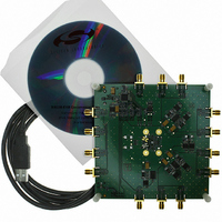
SI5338-EVB
Description
BOARD EVALUATION SI5338
Manufacturer
Silicon Laboratories Inc
Datasheet
1.SI5338B-A-GM.pdf
(42 pages)
Specifications of SI5338-EVB
Main Purpose
Timing, Clock Generator
Embedded
No
Utilized Ic / Part
Si5338
Primary Attributes
160 kHz to 700 MHz in LVPECL/LVDS,
Secondary Attributes
USB Based GUI to Program, I2C/SMBus Compatible Interface, 1.8, 2.5, or 3.3 V
For Use With/related Products
Si5330/34/38 Family
Lead Free Status / RoHS Status
Lead free / RoHS Compliant
Lead Free Status / RoHS Status
Lead free / RoHS Compliant, Lead free / RoHS Compliant
Other names
336-1556


Si5338
3.5.1. Ordering a Custom NVM Configuration
The Si5338 is orderable with a factory-programmed
custom NVM configuration. This is the simplest way of
using the Si5338 since it generates the desired output
frequencies at power-up or after a power-on reset
(POR). This default configuration can be reconfigured in
RAM through the I
“3.5.2. Creating a New Configuration for RAM”).
Custom 7-bit I
Note that for the A/B/C devices, the I
is the logical “or” of the I
and the state of the I2C_LSB pin. If I2C_LSB pin
functionality is required, custom I
only be even numbers. For all other variants of the
device, custom I
numbers. See “AN411: Configuring the Si5338” for
more details.
The first step in ordering a custom device is generating
an NVM file which defines the input and output clock
frequencies and signal formats. This is easily done
using the ClockBuilder Desktop software (see "3.1.1.
ClockBuilder™ Desktop Software" on page 16). This
GUI based software generates an NVM file, which is
used by the factory to manufacture custom parts. Each
custom part is marked with a unique part number
identifying the specific configuration (e.g., Si5338C-
A00100-GM). Consult your local sales representative
for more details on ordering a custom Si5338.
3.5.2. Creating a New Configuration for RAM
Any Si5338 device can be configured by writing to
registers in RAM through the I
factory programmed device must be configured in this
manner.
The first step is to determine all the register values for
the required configuration. This can be accomplished by
one of two methods.
1. Create a device configuration (register map) using
20
ClockBuilder Desktop (v3.0 or later; see "3.1.1.
ClockBuilder™ Desktop Software" on page 16).
a. Configure the frequency plan.
b. Configure the output driver format and supply
c. Configure frequency and/or phase inc/dec (if
d. Configure spread spectrum (if desired).
e. Configure for zero-delay mode (if desired,
f.
g. Save the configuration using the Options >
voltage.
desired).
see "3.10.6. Zero-Delay Mode" on page 26).
If needed go to the Advanced tab and make
additional configurations.
2
C addresses may also be requested.
2
C addresses may be even or odd
2
C interface after power-up (see
2
C address LS bit in Register 27
2
C interface. A non-
2
C addresses may
2
C LS bit address
Rev. 1.0
2. Create a device configuration, register by register,
3.5.3. Writing a Custom Configuration to RAM
Writing a new configuration (register map) to the RAM
consists of pausing the LOL state-machine, writing new
values to the IC accounting for the write-allowed mask
(see AN411, “14. Si5338 Registers”), validating the
input clock or crystal, locking the PLL to the input with
the new configuration, restarting the LOL state-
machine, and calibrating the VCO for robust operation
across temperature. The flow chart in Figure 9
enumerates the details:
Note: The write-allowed mask specifies which bits must be
using AN411.
read and modified before writing the entire register
byte (a.k.a. read-modify-write). “AN428: Jump Start: In-
System, Flash-Based Programming for Silicon Labs’
Timing Products” illustrates the procedure defined in
Section 3.5.2 with ANSI C code.
Save Register Map File or Options > Save C
code Header.
Related parts for SI5338-EVB
Image
Part Number
Description
Manufacturer
Datasheet
Request
R

Part Number:
Description:
KIT PROG FIELD SI5338/4/0
Manufacturer:
Silicon Laboratories Inc
Datasheet:

Part Number:
Description:
Programmers & Debuggers Si5338/4/0 field programming kit
Manufacturer:
Silicon Laboratories Inc
Datasheet:
Part Number:
Description:
SMD/C°/SINGLE-ENDED OUTPUT SILICON OSCILLATOR
Manufacturer:
Silicon Laboratories Inc
Part Number:
Description:
Manufacturer:
Silicon Laboratories Inc
Datasheet:
Part Number:
Description:
N/A N/A/SI4010 AES KEYFOB DEMO WITH LCD RX
Manufacturer:
Silicon Laboratories Inc
Datasheet:
Part Number:
Description:
N/A N/A/SI4010 SIMPLIFIED KEY FOB DEMO WITH LED RX
Manufacturer:
Silicon Laboratories Inc
Datasheet:
Part Number:
Description:
N/A/-40 TO 85 OC/EZLINK MODULE; F930/4432 HIGH BAND (REV E/B1)
Manufacturer:
Silicon Laboratories Inc
Part Number:
Description:
EZLink Module; F930/4432 Low Band (rev e/B1)
Manufacturer:
Silicon Laboratories Inc
Part Number:
Description:
I°/4460 10 DBM RADIO TEST CARD 434 MHZ
Manufacturer:
Silicon Laboratories Inc
Part Number:
Description:
I°/4461 14 DBM RADIO TEST CARD 868 MHZ
Manufacturer:
Silicon Laboratories Inc
Part Number:
Description:
I°/4463 20 DBM RFSWITCH RADIO TEST CARD 460 MHZ
Manufacturer:
Silicon Laboratories Inc
Part Number:
Description:
I°/4463 20 DBM RADIO TEST CARD 868 MHZ
Manufacturer:
Silicon Laboratories Inc
Part Number:
Description:
I°/4463 27 DBM RADIO TEST CARD 868 MHZ
Manufacturer:
Silicon Laboratories Inc
Part Number:
Description:
I°/4463 SKYWORKS 30 DBM RADIO TEST CARD 915 MHZ
Manufacturer:
Silicon Laboratories Inc