EVB-USB2514Q36-BAS SMSC, EVB-USB2514Q36-BAS Datasheet - Page 25
EVB-USB2514Q36-BAS
Manufacturer Part Number
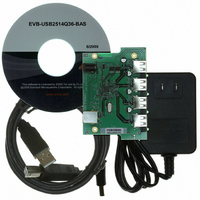
EVB-USB2514Q36-BAS
Description
BOARD EVAL FOR USB2514/USB2514I
Manufacturer
SMSC
Specifications of EVB-USB2514Q36-BAS
Main Purpose
Interface, USB 2.0 Hub
Embedded
No
Utilized Ic / Part
USB2514, USB2514I
Primary Attributes
Quad Port Hub, High Speed (480Mbps), I2C/SMBus
Secondary Attributes
Overcurrent Protection, Port Power Switching, ESD Protection
Interface Type
USB
Operating Supply Voltage
5 V
Product
Interface Modules
Lead Free Status / RoHS Status
Lead free / RoHS Compliant
For Use With/related Products
USB2514
Other names
638-1043
EVB-USB2514Q36-BAS (USB2514/USB2514I)
EVB-USB2514Q36-BAS (USB2514/USB2514I)
Available stocks
Company
Part Number
Manufacturer
Quantity
Price
Company:

Part Number:
EVB-USB2514Q36-BAS
Manufacturer:
Standard
Quantity:
1


USB 2.0 Hi-Speed Hub Controller
Datasheet
SMSC USB251x
NON_REM[1]
CFG_SEL[0]
CFG_SEL[1]
CFG_SEL[2]
SMBDATA /
SMBCLK /
RESET_N
SYMBOL
HS_IND /
SDA /
SCL /
BUFFER
I/OSD12
I/OSD12
TYPE
I/O12
IS
I
Table 5.2 USB251x Pin Descriptions (continued)
Serial Data signal (SDA)
Server Message Block Data signal (SMBDATA)
Non-removable Port Strap Option
If this strap is enabled by package and configuration settings (see
this pin will be sampled (in conjunction with LOCAL_PWR / SUSP_IND /
NON_REM[0]) at RESET_N negation to determine if ports [7:1] contain
permanently attached (non-removable) devices:
NON_REM[1:0] = ‘00’, All ports are removable.
NON_REM[1:0] = ‘01’, Port 1 is non-removable.
NON_REM[1:0] = ‘10’, Ports 1 & 2 are non-removable.
NON_REM[1:0] = ‘11’, When available, ports 1 2 & 3 are non-removable.
RESET Input
The system can reset the chip by driving this input low. The minimum active
low pulse is 1 μs.
Serial Clock (SCL)
System Management Bus Clock (SMBCLK)
Configuration Select: The logic state of this multifunction pin is internally
latched on the rising edge of RESET_N (RESET_N negation), and will
determine the hub configuration method as described in
Configuration
Hi-Speed Upstream Port Indicator
HS_IND: Hi-speed Indicator for upstream port connection speed.
The active state of the LED will be determined as follows:
CFG_SEL[1] = ‘0’,
HS_IND is active high,
CFG_SEL[1] = ‘1’,
HS_IND is active low,
‘Asserted’ = the hub is connected at HS
‘Negated’ = the hub is connected at FS
Configuration Programming Select
CFG_SEL[1]: The logic state of this pin is internally latched on the rising edge
of RESET_N (RESET_N negation), and will determine the hub configuration
method as described in
Configuration Programming Select
The logic state of this pin is internally latched on the rising edge of RESET_N
(RESET_N negation), and will determine the hub configuration method as
described in
pin is unavailable, then the logic is internally tied to ‘0’.
SERIAL PORT INTERFACES
Table 8.1, "Hub Configuration
Options".
DATASHEET
25
Table 8.1, "Hub Configuration
DESCRIPTION
Options". When the CFG_SEL[2]
Options".
Table 8.1, "Hub
Revision 1.1 (04-26-10)
Table
8.1),
Related parts for EVB-USB2514Q36-BAS
Image
Part Number
Description
Manufacturer
Datasheet
Request
R

Part Number:
Description:
BOARD EVAL FOR USB2514 48-QFN
Manufacturer:
SMSC
Datasheet:
Part Number:
Description:
Networking Modules & Development Tools USB2514 Evaluation Board
Manufacturer:
SMSC
Datasheet:

Part Number:
Description:
FAST ETHERNET PHYSICAL LAYER DEVICE
Manufacturer:
SMSC Corporation
Datasheet:
Part Number:
Description:
357-036-542-201 CARDEDGE 36POS DL .156 BLK LOPRO
Manufacturer:
SMSC Corporation
Datasheet:
Part Number:
Description:
357-036-542-201 CARDEDGE 36POS DL .156 BLK LOPRO
Manufacturer:
SMSC Corporation
Datasheet:
Part Number:
Description:
357-036-542-201 CARDEDGE 36POS DL .156 BLK LOPRO
Manufacturer:
SMSC Corporation
Datasheet:
Part Number:
Description:
4-PORT USB2.0 HUB CONTROLLER
Manufacturer:
SMSC Corporation
Datasheet:
Part Number:
Description:
Manufacturer:
SMSC Corporation
Datasheet:
Part Number:
Description:
Manufacturer:
SMSC Corporation
Datasheet:
Part Number:
Description:
FDC37C672ENHANCED SUPER I/O CONTROLLER WITH FAST IR
Manufacturer:
SMSC Corporation
Datasheet:
Part Number:
Description:
COM90C66LJPARCNET Controller/Transceiver with AT Interface and On-Chip RAM
Manufacturer:
SMSC Corporation
Datasheet:
Part Number:
Description:
Manufacturer:
SMSC Corporation
Datasheet:
Part Number:
Description:
Manufacturer:
SMSC Corporation
Datasheet:
Part Number:
Description:
Manufacturer:
SMSC Corporation
Datasheet: