NCV7708AGEVB ON Semiconductor, NCV7708AGEVB Datasheet - Page 12
NCV7708AGEVB
Manufacturer Part Number
NCV7708AGEVB
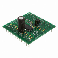
Description
EVAL BOARD FOR NCV7708AG
Manufacturer
ON Semiconductor
Specifications of NCV7708AGEVB
Design Resources
NCV7708 EVB BOM NCV7708GEVB Gerber Files NCV7708 EVB Schematic
Main Purpose
Power Management, Half H-Bridge Driver (Internal FET)
Embedded
No
Utilized Ic / Part
NCV7708
Primary Attributes
6 Channel High & Low Side Internal Switch
Secondary Attributes
SPI Interface
Silicon Manufacturer
On Semiconductor
Silicon Core Number
NCV7708A
Kit Application Type
Driver - Bridge
Application Sub Type
Half Bridge Driver
Development Tool Type
Hardware - Eval/Demo Board
Rohs Compliant
No
Lead Free Status / RoHS Status
Lead free / RoHS Compliant
For Use With/related Products
NCV7708AG
Other names
NCV7708AGEVBOS


Applications Drawing
which this part can drive a multitude of loads.
H−Bridge Driver Configuration
driver independently. When the device is set up in an
H−Bridge configuration, the software design has to take care
of avoiding simultaneous activation of connected HS and LS
transistors. Resulting high shoot through currents could
cause irreversible damage to the device.
The applications drawing below displays the range with
Any combination of motors and high side drivers can be designed in. This allows for flexibility in many systems.
The NCV7708A has the flexibility of controlling each
Lead #1
+
Lead #8 (one of 8 thermal leads)
Active Area (red)
With and Without Mold Compound
Molded as
Package Construction
OUTHx
OUTLx
GND
OUTHx
VSx
OUTLx
VSx
GND
1
/
4
Figure 5. Application Drawing
Symmetry
1
http://onsemi.com
M
Thermal Model
12
Overvoltage Clamping − Driving Inductive Loads
in a single−side−mode (LS or HS switch, no freewheeling
path), the NCV7708A provides internal clamping diodes.
Thus any load type can be driven without the requirement of
external freewheeling diodes. Due to high power dissipation
during clamping, the maximum energy capability of the
driver transistor has to be considered.
To avoid excessive voltages when driving inductive loads
1. H−Bridge Driver configuration
2. Low Side Driver
3. High Side Driver
Various copper areas used
OUTHx
OUTLx
VSx
GND
for heat spreading
3
2
Related parts for NCV7708AGEVB
Image
Part Number
Description
Manufacturer
Datasheet
Request
R

Part Number:
Description:
The NCV7708A is a fully protected Hex Half Bridge Driver designed specifically for automotive and industrial motion control applications. The six low and high side drivers are freely configurable and can be controlled separately. This allows for high
Manufacturer:
ON Semiconductor
Datasheet:
Part Number:
Description:
The NCV7708 is a fully protected Hex Half Bridge Driver designed specifically for automotive and industrial motion control applications. The six low and high side drivers are freely configurable and can be controlled separately. This allows for high
Manufacturer:
ON Semiconductor
Datasheet:
Part Number:
Description:
ON Semiconductor [VOLTAGE REGULATOR]
Manufacturer:
ON Semiconductor
Datasheet:
Part Number:
Description:
357-036-542-201 CARDEDGE 36POS DL .156 BLK LOPRO
Manufacturer:
ON Semiconductor
Datasheet:
Part Number:
Description:
357-036-542-201 CARDEDGE 36POS DL .156 BLK LOPRO
Manufacturer:
ON Semiconductor
Datasheet:
Part Number:
Description:
357-036-542-201 CARDEDGE 36POS DL .156 BLK LOPRO
Manufacturer:
ON Semiconductor
Datasheet:
Part Number:
Description:
357-036-542-201 CARDEDGE 36POS DL .156 BLK LOPRO
Manufacturer:
ON Semiconductor
Datasheet:
Part Number:
Description:
357-036-542-201 CARDEDGE 36POS DL .156 BLK LOPRO
Manufacturer:
ON Semiconductor
Datasheet:
Part Number:
Description:
357-036-542-201 CARDEDGE 36POS DL .156 BLK LOPRO
Manufacturer:
ON Semiconductor
Datasheet:
Part Number:
Description:
357-036-542-201 CARDEDGE 36POS DL .156 BLK LOPRO
Manufacturer:
ON Semiconductor
Datasheet:
Part Number:
Description:
357-036-542-201 CARDEDGE 36POS DL .156 BLK LOPRO
Manufacturer:
ON Semiconductor
Datasheet:
Part Number:
Description:
357-036-542-201 CARDEDGE 36POS DL .156 BLK LOPRO
Manufacturer:
ON Semiconductor
Datasheet:
Part Number:
Description:
357-036-542-201 CARDEDGE 36POS DL .156 BLK LOPRO
Manufacturer:
ON Semiconductor
Datasheet:
Part Number:
Description:
Manufacturer:
ON Semiconductor
Datasheet: