VSUPEV2 Microchip Technology, VSUPEV2 Datasheet - Page 17
VSUPEV2
Manufacturer Part Number
VSUPEV2
Description
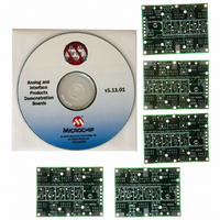
BOARD EVAL FOR MCP4022,4023,4024
Manufacturer
Microchip Technology
Specifications of VSUPEV2
Main Purpose
Power Management, Power Supply Supervisor/Tracker/Sequencer
Embedded
No
Utilized Ic / Part
SOT-23-5, SOT-23-6 Package
Primary Attributes
Voltage Detector & Supervisor
Secondary Attributes
5 Boards & 3 IC's Included
Processor To Be Evaluated
SOT23-5/6
Lead Free Status / RoHS Status
Lead free / RoHS Compliant
Lead Free Status / RoHS Status
Lead free / RoHS Compliant, Lead free / RoHS Compliant


2.5
2004 Microchip Technology Inc.
EVALUATING THE DEVICE
When evaluating a Voltage Supervisor or Voltage Detector device, a minimum set of
test equipment should be available. Table 2-3 shows the recommended test
equipment.
TABLE 2-3:
A typical system that would be used to evaluate the voltage supervisor or voltage
detector device is shown in Figure 2-4. Figure 2-4 also shows an example input and
output waveforms for a voltage supervisor or voltage detector device.
FIGURE 2-4:
Variable Power
Supply
Arbitary
Waveform
Generator
Digital Multi-Meter
(D.M.M.)
Oscilloscope
Test Light (LED)
Test
Point or
V
Hardware
Arbitary Waveform
Generator
Output
OUT
Waveform
Generator
Variable
Arbitary
Supply
Power
or
TEST EQUIPMENT
EVALUATION SYSTEM
Connect to:
V
V
DD
DD
V
V
V
Supervisor
OUT
OUT
OUT
SOT23 Evaluation Board PCB
, V
, V
Detector
Voltage
Voltage
Device V
Output voltage may be indeterminate
SS
SS
or
This allows the voltage to the SOT23 Evaluation Board
to be varied so the device output can be monitored.
This is like a variable power supply, but allows program-
ablity into the input signal that the device will be
subjected to. This also allows a particular waveform to
be repeated (such as a 60 Hz sine wave that varies from
1V to 5V)
Used to indicate the output state (Low or High) of the
Voltage Supervisor/Voltage Detector.
Allows the device conditions and response to be better
evaluated due to the ability to capture this information.
This is useful for faster signals and cases where small
spikes need to be detected.
Used to visually indicate the output state (low or high) of
the Voltage Supervisor/Voltage Detector. Ensure that
the current requirements of this light can be supplied by
the device’s output pin.
DD
out of Valid Operating Range
C2
Test Point
R3
Comment
Oscilloscope
DS51510A-page 13
Related parts for VSUPEV2
Image
Part Number
Description
Manufacturer
Datasheet
Request
R

Part Number:
Description:
Manufacturer:
Microchip Technology Inc.
Datasheet:
Part Number:
Description:
Manufacturer:
Microchip Technology Inc.
Datasheet:
Part Number:
Description:
Manufacturer:
Microchip Technology Inc.
Datasheet:
Part Number:
Description:
Manufacturer:
Microchip Technology Inc.
Datasheet:
Part Number:
Description:
Manufacturer:
Microchip Technology Inc.
Datasheet:
Part Number:
Description:
Manufacturer:
Microchip Technology Inc.
Datasheet:
Part Number:
Description:
Manufacturer:
Microchip Technology Inc.
Datasheet:
Part Number:
Description:
Manufacturer:
Microchip Technology Inc.
Datasheet: