MCP1630DM-NMC1 Microchip Technology, MCP1630DM-NMC1 Datasheet - Page 13
MCP1630DM-NMC1
Manufacturer Part Number
MCP1630DM-NMC1
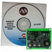
Description
BOARD DEMO FOR MCP1630
Manufacturer
Microchip Technology
Type
Battery Managementr
Datasheet
1.MCP1630DM-NMC1.pdf
(28 pages)
Specifications of MCP1630DM-NMC1
Main Purpose
Power Management, Battery Charger
Embedded
Yes, MCU, 8-Bit
Utilized Ic / Part
MCP1630
Primary Attributes
4 Cells- NiMH, 500mA, 8 V ~ 15 V Input
Secondary Attributes
Simple Fuel Gauge, 3 Charge Modes, Over: Current/Voltage/Charge Protection
Product
Power Management Modules
For Use With/related Products
MCP1630
Lead Free Status / RoHS Status
Contains lead / RoHS non-compliant
Lead Free Status / RoHS Status
Lead free / RoHS Compliant, Contains lead / RoHS non-compliant


© 2006 Microchip Technology Inc.
2.3.1.3
The MCP1630 NiMH Battery Charger Demo Board has two LEDs. D
is used to indicate when input power is available. When the +12V input is connected,
D
These can be off, red, green or both on (amber). To conserve energy, D
illuminated when there is no input power. If both LEDs are off, that is an indication there
is no power supplied to the board input.
Under normal power-up conditions, the charger will begin with a 50 mA trickle charge.
The microcontroller will then check the status of the batteries to ensure that they are
present, their temperature is within range and the series voltage is within specified
charging limits. For visual LED charge status, a dual-color SOT-23 LED is used (D
With no input connected and 4 NiMH batteries used as a load, the MCP1630 NiMH
Battery Charger Demo Board will consume approximately 29 μA from the battery.
A temperature sensor is provided for charge termination. The sensor (U2) is located on
the back of the printed circuit board. To utilize this feature, batteries should be in
physical contact with the temperature sensor.
Programming:
1
- D
- D
will be illuminated. The other LED (D
- J1 can be used as a Flash programming port to modify the code for proto-
9
9
type applications. The pinout of J1 matches the required pinout for the
MPLAB
Status Indication Normal Charge Modes:
Status Indication for Fault Modes:
Initial Trickle Charge (50 mA)
Fast Charge (500 mA)
Final Trickle Charge (50 mA)
Top Off Charge (25 mA)
Charge Complete (0 mA)
Initial Trickle Charge (50 mA)
Overvoltage Initial
(Restart Initiated)
Overvoltage
(Persistent, Latched-off after 9
attempts)
Overcurrent
STATUS LEDS
Fault Mode Board Status
Normal Charge Mode
®
ICD 2 programmer.
Board Status
9
) has two LEDs built into a SOT-23 package.
ON (Blinking Faster)
ON (Blinking)
ON Blinking
ON (Solid)
ON (Solid)
ON (Solid)
Red LED
Red LED
OFF
OFF
OFF
ON (Blinking, 1 sec)
1
is a red LED that
Green LED
Green LED
ON (Solid)
ON (Solid)
ON (Solid)
DS51505B-page 9
9
OFF
OFF
OFF
OFF
OFF
is never
9
).
Related parts for MCP1630DM-NMC1
Image
Part Number
Description
Manufacturer
Datasheet
Request
R

Part Number:
Description:
BOARD DEMO BOOST AUTO INPUT
Manufacturer:
Microchip Technology
Datasheet:

Part Number:
Description:
BOARD CONV DEMO MCP1630 TRPL-OUT
Manufacturer:
Microchip Technology
Datasheet:

Part Number:
Description:
BOARD DEMO MCP1630 BIAS SUPPLY
Manufacturer:
Microchip Technology
Datasheet:

Part Number:
Description:
BOARD DEMO BOOST COUPLED INDUCTR
Manufacturer:
Microchip Technology
Datasheet:

Part Number:
Description:
BOARD DEM MCP1630 BOOST MODE LED
Manufacturer:
Microchip Technology
Datasheet:

Part Number:
Description:
Manufacturer:
Microchip Technology Inc.
Datasheet:
Part Number:
Description:
Manufacturer:
Microchip Technology Inc.
Datasheet:
Part Number:
Description:
Manufacturer:
Microchip Technology Inc.
Datasheet:
Part Number:
Description:
Manufacturer:
Microchip Technology Inc.
Datasheet:
Part Number:
Description:
Manufacturer:
Microchip Technology Inc.
Datasheet:
Part Number:
Description:
Manufacturer:
Microchip Technology Inc.
Datasheet: